DC input points: 32 points.
Input voltage and current: 3/7mA, DC12/24V.
Response time: 10ms.
Positive pole sharing.
16 point /1 a public side.
Output points: 24 points.
Output voltage and current: DC12/24V, 0.5A/1 point, 3.2A/1 common end.
Response time: 2ms.
8 point /1 a public end, 4 point /1 a public end A2NCPUP21-S1.
Outputt form: transistor output, leakage type.
36 point terminal table * 2.
Number of stations: 8 stops.
Compact remote I/O unit.
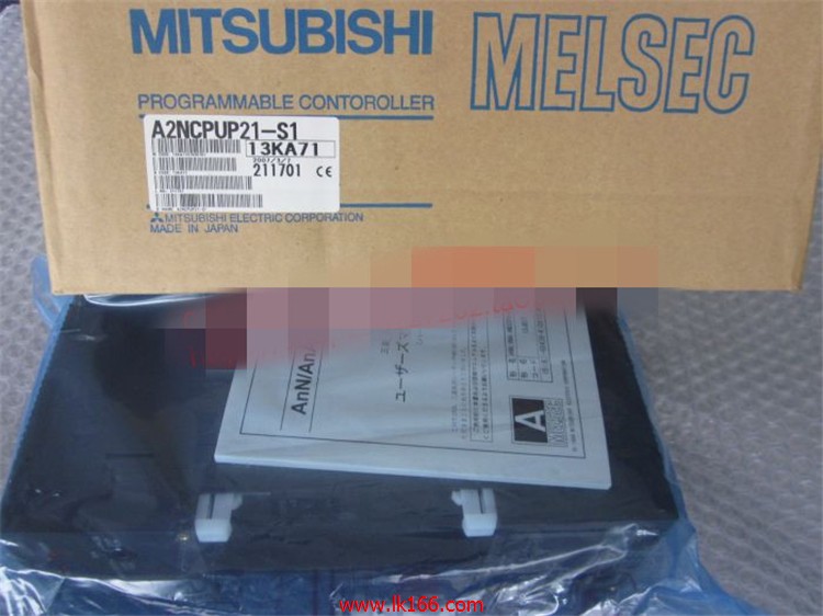
According to the control requirements of the system, using the appropriate design method to design MITSUBISHI PLC program A2NCPUP21-S1.
Procedures to meet the requirements of system control as the main line,
Write one by one to achieve the control function or the sub task of the program,
Gradually improve the functions specified by the system A2NCPUP21-S1.
MITSUBISHI PLC detection, fault diagnosis and display and other procedures.
These procedures are relatively independent, generally in the basic completion of the program design and then add.
Hardware simulation method is to use a number of hardware equipment to simulate the generation of the signal,
The signals are connected to the input end of the PLC system in a hard wired way, and the timeliness is strong MITSUBISHI A2NCPUP21-S1.
Software simulation method is in the MITSUBISHI PLC in the preparation of a set of simulation program,
The simulation provides the field signal, which is simple and easy to operate, but it is not easy to guarantee the timeliness MITSUBISHI A2NCPUP21-S1.
Simulation of the process of debugging, debugging method can be used to segment, and the monitoring function of programmer. Output type: transistor output, drain type.
Output points: 32 points MITSUBISHI A2NCPUP21-S1.
OFF leakage current: 0.25mA.
Output protection function.
Rated load voltage / current: DC24V/DC24V/0.1A.
External connection: 1 wire.
Fast connector type.
Simple wiring through quick connector.
Can be installed along the 6 direction.
MITSUBISHI PLC program simulation debugging
The basic idea of program simulation debugging is,
In order to facilitate the form of simulation to generate the actual state of the scene,
Create the necessary environmental conditions for the operation of the program.
Depending on the way the field signals are generated,
The simulation debugging has two forms of hardware simulation and software simulation.
Input and output points: 1024 points.
Input / output data points: 1024 points.
Program capacity: 14K.
Basic command processing speed (LD command) s:1.0.
Coaxial data communication line function.
User program storage capacity: it is a measure of how much the user application can store the number of indicators.
Usually in words or K words as units. 16 bit binary number is a word,
Every 1024 words are 1K words. PLC to store instructions and data in words.
General logical operation instructions each account for 1 words. Timer / counter,
Shift instruction accounted for 2 words. Data operation instructions for 2~4.
Integral type: the PLC components are installed together or a few pieces of printed circuit board,
And together with the power supply iinstalled in the casing to form a single overall called the host or the basic unit, small, ultra small PLC using this structure A2NCPUP21-S1.
Modular: PLC is the basic components of a separate module.
Medium and large PLC used this way. Easy maintenance.


