 LK Automation Limited
Screw terminal table type.
Voltage / current output module.
Number of channels: 2 channels.
Number of stations: 1 stops.
Station type: remote equipment station.
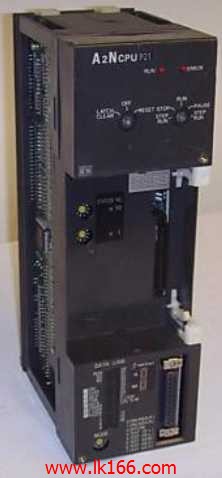
MITSUBISHI PLC hardware implementation
Hardware implementation is mainly for the control cabinet and other hardware design and field construction A2NCPUP21.
Design control cabinet and thee operating table and other parts of the electrical wiring diagram and wiring diagram.
Electrical interconnection diagram of each part of the design system A2NCPUP21.
According to the construction drawings of the site wiring, and carry out a detailed inspection.
Because the program design and hardware implementation can be carried out at the same time,
So the design cycle of the MITSUBISHI PLC control system can be greatly reduced A2NCPUP21.
MITSUBISHI PLC online debugging.
On-line debugging is the process that will through the simulation debugging to further carry on the on-line unification to adjust.
On-line debugging process should be step by step,
From MITSUBISHI PLC only connected to the input device, and then connect the output device, and then connect to the actual load and so on and so on step by step MITSUBISHI A2NCPUP21.
If you do not meet the requirements, the hardware and procedures for adjustment.
Usually only need to modify the part of the program can be. Input type: DC input, positive common end.
Input points: 16 points MITSUBISHI A2NCPUP21.
Enter the response time: 0.2ms the following.
Rated input voltage / current: DC24V/5mA.
Output form: transistor output, leakage type.
Output points: 16 points.
OFF leakage current: 0.25mA.
Output protection function.
Rated load voltage / current: DC24V/0 MITSUBISHI A2NCPUP21.1A.
External connection: 1 line /1 line type.
Fast connector type.
Simple wiring through quick connector.
Can be installed along the 6 direction.
MITSUBISHI PLC program simulation debugging
The basic idea of program simulation debugging is,
In order to facilitate the form of simulation to generate the actual state of the scene,
Create the necessary environmental conditions for the operation of the program.
Depending on the way the field signals are generated,
The simulation debugging has two forms of hardware simulation and software simulation.
Input and output points: 512 points.
Input / output data points: 512 points.
Program capacity: 14K.
Basic command processing speed (LD command) s:1.0.
Optical data communication line.
User program storage capacity: it is a measure of how much the user application can store the number of indicators.
Usually in words or K words as units. 16 bit binary number is a word,
Every 1024 words are 1K words. PLC to store instructions and data in words.
General logical operation instructions each account for 1 words. Timer / counter,
Shift instruction accounted for 2 words. Data operation instructions for 2~4.
Integral type: the PLC components are installed together or a few pieces of printed circuit board,
And together with the power supply iinstalled in the casing to form a single overall called the host or the basic unit, small, ultra small PLC using this structure A2NCPUP21.
Modular: PLC is the basic components of a separate module.
Medium and large PLC used this way. Easy maintenance.