 LK Automation Limited
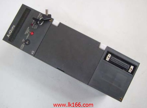
A3UCPU MITSUBISHI A3UCPU
Brand:
MITSUBISHI
Name: CPU unit
Model: A3UCPU
Input and output points: 2048 points.
Input / output data points: 8192 points.
Program capacity: 30K.
Basic command processing speed (LD command) s:0.15.
Integral type: the PLC components are installed together or a few pieces of printed circuit board,
And together with the power supply installed in the casing to form a single overall called the host or the basic unit, small, ultra small PLC using this structure.
Modular: PLC is the basic components of a separate module.
Medium and large PLC used this way. Easy maintenance.
Each scanning process. Focus on the input signal sampling. Focus on the output signal to refresh.
Input refresh process. When the input port is closed,
Program in the implementation phase, the input end of a new state, the new state can not be read.
Only when the program is scanned, the new state is read.
A scan cycle is divided into the input sample, the program execution, the output refresh.
The contents of the component image register are changed with the change of the execution of the program.
The length of the scan cycle is determined by the three.
CPU the speed of executing instructions.
Time of instruction.
Instruction count.
Due to the adoption of centralized sampling.
Centralized output mode.
There exist input / output hysteresis phenomena, i.e., the input / output response delay.
User program storage capacity: it is a measure of how much the user application can store the number of indicators.
Usually in words or K words as units. 16 bit binary number is a word,
Every 1024 words are 1K words. PLC to store instructions and data in words.
General logical operation instructions each account for 1 words. Timer / counter,
Shift instruction accounted for 2 words. Data operation instructions for 2~4.
...More relevant models >>>>
Name: CPU unit
Model: A3UCPU
Input and output points: 2048 points.
Input / output data points: 8192 points.
Program capacity: 30K.
Basic command processing speed (LD command) s:0.15.
Integral type: the PLC components are installed together or a few pieces of printed circuit board,
And together with the power supply installed in the casing to form a single overall called the host or the basic unit, small, ultra small PLC using this structure.
Modular: PLC is the basic components of a separate module.
Medium and large PLC used this way. Easy maintenance.
Each scanning process. Focus on the input signal sampling. Focus on the output signal to refresh.
Input refresh process. When the input port is closed,
Program in the implementation phase, the input end of a new state, the new state can not be read.
Only when the program is scanned, the new state is read.
A scan cycle is divided into the input sample, the program execution, the output refresh.
The contents of the component image register are changed with the change of the execution of the program.
The length of the scan cycle is determined by the three.
CPU the speed of executing instructions.
Time of instruction.
Instruction count.
Due to the adoption of centralized sampling.
Centralized output mode.
There exist input / output hysteresis phenomena, i.e., the input / output response delay.
User program storage capacity: it is a measure of how much the user application can store the number of indicators.
Usually in words or K words as units. 16 bit binary number is a word,
Every 1024 words are 1K words. PLC to store instructions and data in words.
General logical operation instructions each account for 1 words. Timer / counter,
Shift instruction accounted for 2 words. Data operation instructions for 2~4.
10BASE5/10BASE2
When communicating in the PLC network of MITSUBISHI,
There is no sense of difference and discontinuity in the network,
Can carry on the remote monitoring, modification, debugging and other work of data communication and program,
Without taking into account the level and type of network MITSUBISHI A3UCPU.
MELSECNET/H and CC-Link use the way of loop communication,
Periodically automatically send and receive messages,
Does not require specialized data communication procedures,
Simple parameters can be set A3UCPU
MELSECNET/H and CC-Link are used to transmit and receive the broadcast mode,
This can be done on the network data sharing.
For the use of Ethernet, MELSECNET/H, CC-Link network,
Can set the network parameters and various functions, simple and convenient in the Developer GX software screen MITSUBISHI A3UCPU. Enter 16 points.
Voltage and current: 14mA DC24V.
Response time: 8ms.
16 point 1 public end, 20 point terminal.
Detailed analysis of the process and work characteristics of the controlled object,
To understand the coordination between the controlled object machine, electricity and liquid,
The control requirements of the controlled object for MITSUBISHI PLC control system are put forward,
Determine the control program, to develop a design task book MITSUBISHI A3UCPU.
How to determine the input / output device of MITSUBISHI plc.
According to the control requirements of the system,
All input devices and output devices required for the determination of the system,
To determine the input / output device related to the MITSUBISHI PLC,
To determine the I/O PLC points. SI/QSI/H-PCF/ wide range H-PCF fiber optic cable.
Double loop.
PC inter network (management station / station) / remote I/O network (remote control station).
How to choose MITSUBISHI PLC.
MITSUBISHI PLC options include the choice of MITSUBISHI PLC models, capacity, I/O module, power, etc..
MITSUBISHI PLC distribution I/O points and design MITSUBISHI PLC peripheral hardware circuit
Draw the I/O point of the PLC and the input / output device connection diagram or the corresponding table,
This part also can be carried out in second steps.
DDesign PLC peripheral hardware circuit A3UCPU.
Draw the electrical wiring diagram of the other parts of the system,
Including the main circuit and the control circuit does not enter the PLC, etc..
The electrical schematic diagram of the system compoosed of I/O PLC connection diagram and PLC peripheral electrical circuit diagram A3UCPU.
So far the system''s hardware electrical circuit has been determined.
...More relevant models >>>>


