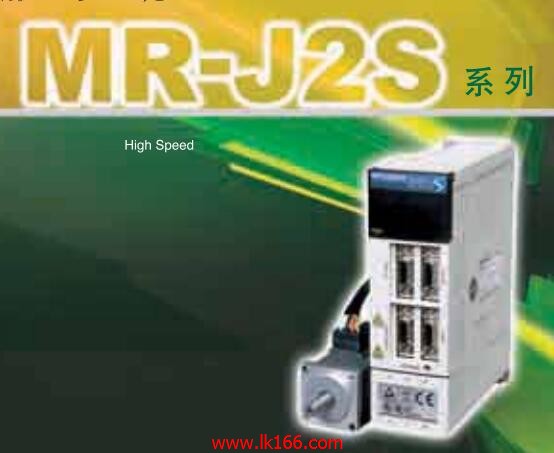
MR-J2S-350CP
- Brand: MITSUBISHI
- Country: JAPAN
- Name: Built in positioning function servo amplifier
- Model: MR-J2S-350CP
- Price: U.S.$ 3298.31
MITSUBISHI MR-J2S-350CP
Input / output points: 4096 points.
Number of input and output elements: 8192.
Program capacity: 500 K step.
Processing speed: 0.0095 s.
Program memory capacity: 2000 KB.
Support USB and network.
Support installed memory card.
Providing high speed communication between multiple CPU.
Shorten the fixed scan interrupt time, high precision device MR-J2S-350CP.
The minimum interval of the fixed period interrupt program is reduced to 100 s MR-J2S-350CP
The high speed signal can be accurately obtained, which makes the contribution to the higher precision of the device.
High speed and high precision machine control by multi CPU.
By parallel processing of the linear and multi CPU high-speed communication (cycle 0 MR-J2S-350CP. 88ms) of the parallel control program, the high speed control .
Multi CPU high speed communication cycle and motion control synchronization, so it can achieve the maximization of computing efficiency.
In addition, the latest movement control CPU in performance is 2 times the previous model,
To ensure high speed and high accuracy of the machine control.Power: 0.75kw MR-J2S-350CP.
Purpose: to suppress the power harmonics .
Improve the power factor, reduce the input side of the high harmonic current.
Make sure that this option is installed in the FR-A820-03800 (75K) and FR-A840-02160 (75K) and above capacity and above capacity.
At the same time the installation options in the use of 75kW and above motor. (the IP55 series has a built-in DC reactor.)
According to the motor power used to select the DC reactor.
(when the inverter capacity is greater than the motor capacity, is still based on the motor capacity to choose.) 3C-2V/5C-2V coaxial cable.
Double loop.
PC inter network (management station / station) / remote I/O network (remote control station).
How to choose MITSUBISHI PLC.
MITSUBISHI PLC options include the choice of MITSUBISHI PLC models, capacity, I/O module, power, etc..
MITSUBISHI PLC distribution I/O points and design MITSUBISHI PLC peripheral hardware circuit
Draw the I/O point of the PLC and the input / output device connection diagram or the corresponding table,
This part also can be ccarried out in second stteps MR-J2S-350CP.
Design PLC peripheral hardware circuit.
Draw the electrical wiring diagram of the other parts of the system,
Including the main circuit and the control circuit does not enter the PLC, etc..
The electrical schematic diagram of the system compooseed of I/O PLC connection diagram and PLC peripheral electrical circuit diagram MR-J2S-350CP.
So far the system''s hardware electrical circuit has been determined.
MR-J2S-350CP Operation manual/Instructions/Model selection sample download link: /searchDownload.html?Search=MR-J2S-350CP&select=5
...more relevant model market price >>>>
Related products
MITSUBISHI
Universal interface servo amplifier
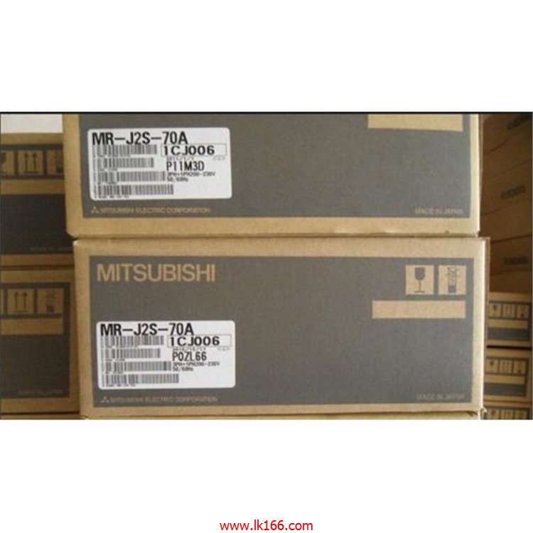
MR-J2S-70A

"MITSUBISHI general purpose AC servo amp
MITSUBISHI
Built in positioning function servo amplifier
MR-J2S-200CP-S084

"MITSUBISHI general purpose AC servo amp
MITSUBISHI
SSCNET interface servo amplifier
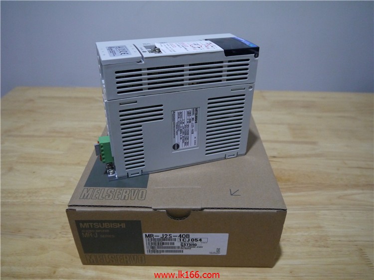
MR-J2S-40B

MITSUBISHI general purpose AC servo ampl
MITSUBISHI
SSCNET interface servo amplifier
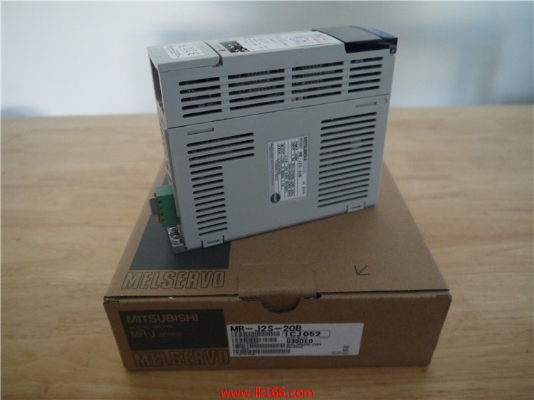
MR-J2S-20B

"MITSUBISHI general purpose AC servo amp

