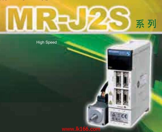
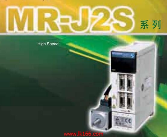
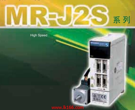
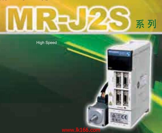
MR-J2S-10B-T004

- Brand: MITSUBISHI
- Country: JAPAN
- Name:
- Model: MR-J2S-10B-T004
- Price: U.S.$ 867.8
MITSUBISHI MR-J2S-10B-T004
Drive: MR-H_ACN series CC-LINK features.
Rated output: 2.0KW.
The test system is composed of two parts, namely, the servo driver, the motor system and the host computer.
The host computer sends the speed command signal to the servo driver,
Servo drives start to run in accordance with the instructions .
In the course of operation, the running data of the servo system is collected by the host computer and the data acquisition circuit,
And carries on the preservation, the analysis and the display to the data MR-J2S-10B-T004 Because the motor is not loaded in this test system,
So compared with the previous two kinds of testing systems, the system has a relatively small volume,
And the measurement and control circuit of the system is relatively simple,
But it also makes the system can not simulate the actual operation of the servo drive MR-J2S-10B-T004.
Usually, such testing system is only used to test the rotational speed and angular displacement of the tested system under no-load condition,
And can not carry on the comprehensive and accurate test to the servo drive. Type: general purpose AC servo amplifier MR-E series MR-J2S-10B-T004.
Rated output: 0.1kw.
Interface type: analog input interface.
KH003 special mark for Super MR-E.
Servo amplifier terminals are used to reduce the required wiring time.
The connector is located in front of the servo amplifier, which is convenient for cable connection.
The gain adjustment can be easily carried out by the real-time automatic tuning function.
Wide use.
Machining equipment and machine tool feed.
Used for food, packaging equipment and feeding device.
For textile machinery, etc..
Can improve the performance of equipment. Enter 8 points: 24VDC.
4 wire type.
Response time: 1.5ms.
Output 8 points: 24VDC.
Transistor output.
Waterproof connector type.
MITSUBISHI PLC hardware implementation
Hardware implementation is mainly for the control cabinet and other hardware design and field construction.
Design control cabinet and the operating table and other parts of the electrical wiring diagram and wiring diagram.
Electrical interconnection diagram of each part of the design system.
According to the construction drawings of the site wiring, and carry out a detailed inspection.
Because the program design and hardware implementation can be carried out at the same time,
So the design cycle of the MITSUBISHI PLC control system can be greatly reduced.
MITSUBISHI PLC online debugging.
On-line debugging is the process that will through the simulation debugging to furtherr carry on the on-line unification to adjust MR-J2S-10B-T004.
On-line debugging process should be step by step,
From MITSUBISHI PLC only connected to the input device, and then connect the output device, and then connect to the actual load and so on and so on stepp bby step MR-J2S-10B-T004.
If you do not meet the requirements, the hardware and procedures for adjustment.
Usually only need to modify the part of the program can be.
MR-J2S-10B-T004 Operation manual/Instructions/Model selection sample download link: /searchDownload.html?Search=MR-J2S-10B-T004&select=5
...more relevant model market price >>>>
Related products
MITSUBISHI
SSCNET interface servo amplifier
MR-J2S-30KB4

MITSUBISHI general purpose AC servo ampl
MITSUBISHI
Built in program type operational function servo amplifier
MR-J2S-40CL

MITSUBISHI general purpose AC servo ampl
MITSUBISHI
SSCNET interface servo amplifier
MR-J2S-30KB

MITSUBISHI general purpose AC servo ampl
MITSUBISHI
SSCNET interface servo amplifier
MR-J2S-37KB4

MITSUBISHI general purpose AC servo ampl


