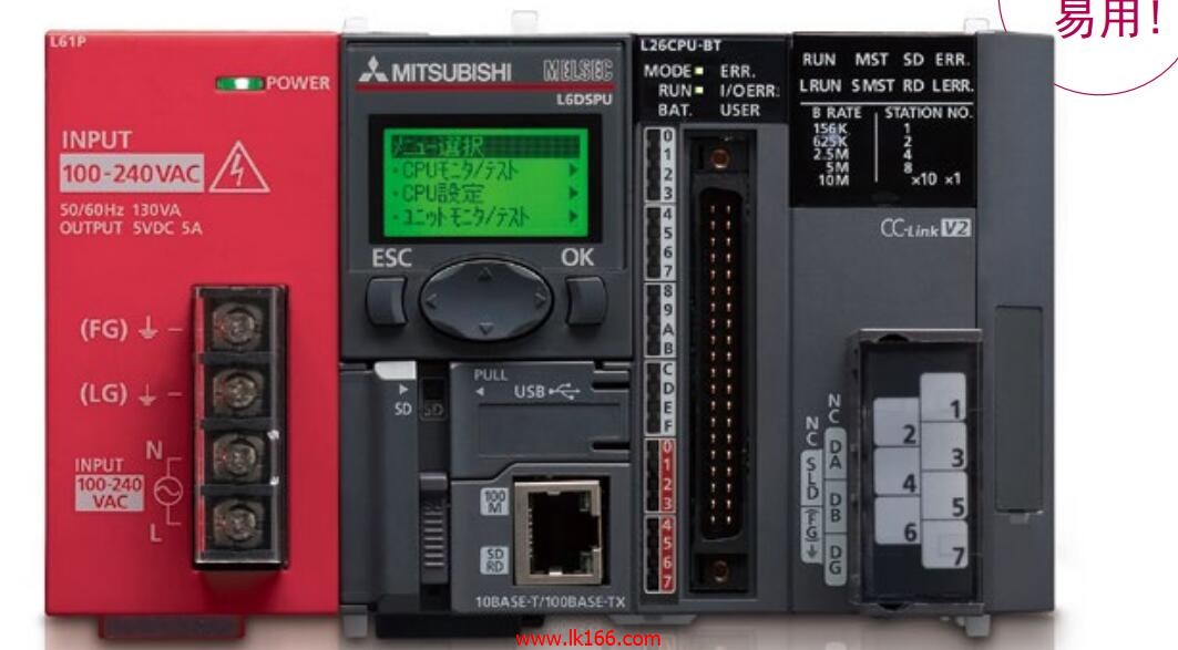
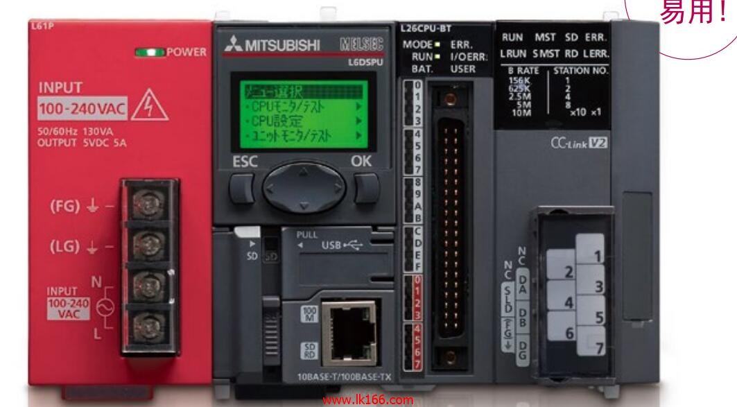
L60TCTT4BW-CM
- Brand: MITSUBISHI
- Country: JAPAN
- Name: Temperature control module
- Model: L60TCTT4BW-CM
- Price: U.S.$ 779.66
MITSUBISHI L60TCTT4BW-CM
Length: 3.0m.
Specification: TB-FX round cable. Type: HC-PQ type.
Output power: 0.05kw.
Rated speed: 3000r/min.
Electromagnetic brake: there.
Key axis: D type shaft.
Motor aspects: the material, structure and processing technology of the servo motor is much higher than that of AC motor,
That is when the driver output current, voltage, frequency change is fast power supply,
The servo motor can change according to the change of the response of the power supply,
Response characteristics and anti overload capacity is much higher than the AC motor drive,
Motor aspects of the serious differences between the two are fundamentally different performance L60TCTT4BW-CM
That is not the inverter output can not change so fast power signal,
But the motor itself can not react,
So in the frequency of the internal algorithm set to protect the motor to do the corresponding overload L60TCTT4BW-CM.
Of course, even without the ability to set the output of the inverter is limited,
Some of the excellent performance of the inverter can be directly driven servo motor. Input type: DC input, positive common end L60TCTT4BW-CM.
Input points: 8 points .
Enter the response time: 1.5ms the following.
Rated input voltage / current: DC24V/5mA.
Output form: transistor output, leakage type.
Output points: 8 points.
OFF leakage current: 0.1mA.
Output protection function: No.
Rated load voltage / current: DC24V/0.5A.
External connection: 3 line /2 line type.
Spring clip terminal.
Do not need to be tightened further or locked with screws, which can reduce the working hours of wiring.
Using 2 pieces of structure of the terminal units, maintenance can be maintained in the same line under the condition of the replacement module.
When installing the module can choose to use the DIN guide rail or screw mounting.
Can be used for the 3 wire sensor input wiring. RS-232:1, RS-422/485:1.
Transmission speed: 0.3 ~ 19.2kpbs.
Computer connection function.
Printer / peripheral device connection, BASIC language function.
The electrical schematic diagram of the system composed of I/O PLC connection diagram and PLC peripheral electrical circuit diagram.
So far the system''s hardware electrical circuit has been determined.
How to choose MITSUBISHI PLC.
MITSUBISHI PLC options include the choice of MITSUBISHI PLC models, capacity, I/O module, power, etc..
MITSUBISHI PLC distriibution I/O points and design MITSUBISHI PLC peripheral hardware circuit
Draw the I/O point of the PLC and the input / output device connection diagram or the corresponding table,
This part also can be carried out in second steps L60TCTT4BW-CM.
Design PLC peripheral hardware circuit. .
Draw the electrical wiring diagram of the other parts of the system,
Including the main circuit and the control circuit does not enter the PLC, etc L60TCTT4BW-CM. .
L60TCTT4BW-CM Operation manual/Instructions/Model selection sample download link: /searchDownload.html?Search=L60TCTT4BW-CM&select=5
...more relevant model market price >>>>
Related products
MITSUBISHI
Temperature control module
L60TCRT4BW-CM

Temperature measurement resistor input.
MITSUBISHI
Temperature control module
L60TCTT4BW-CM

Thermocouple input.
Numer of input chan
MITSUBISHI
Temperature control module
L60TCTT4-CM

Thermocouple input.
Numer of input chan


