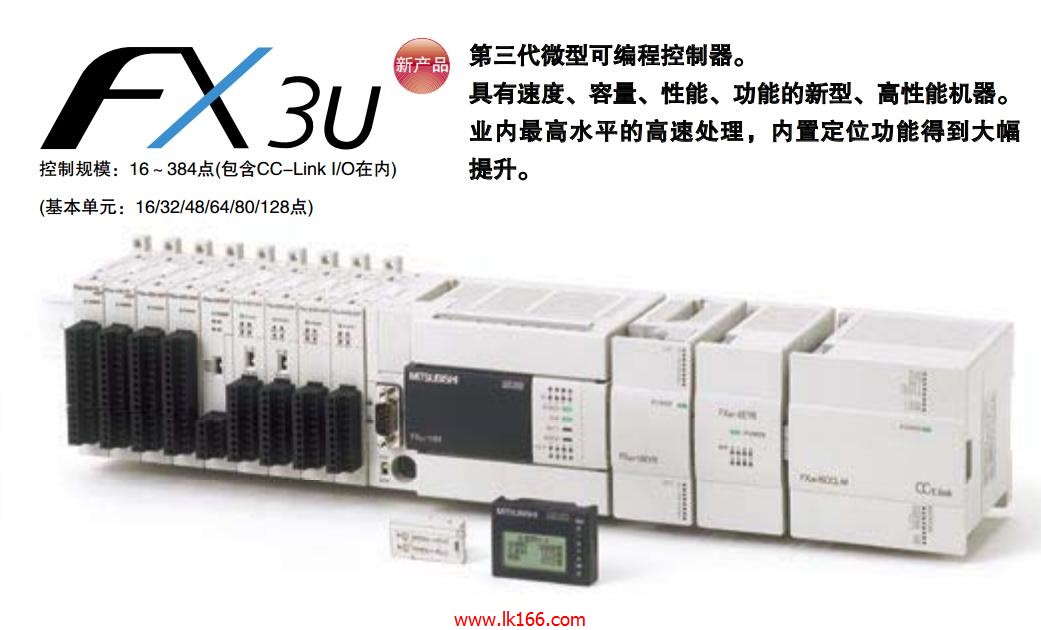
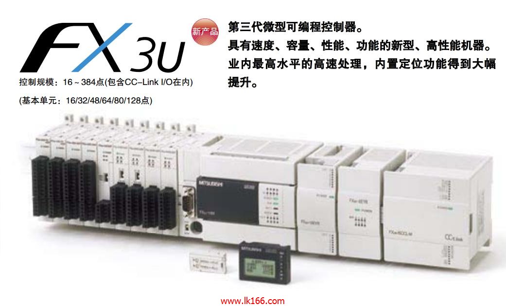
FX3U-16MT/ESS
- Brand: MITSUBISHI
- Country: JAPAN
- Name: PLC
- Model: FX3U-16MT/ESS
- Price: U.S.$ 789.83
MITSUBISHI FX3U-16MT/ESS
Length: 1.5m.
Specification: TB-FX round cable. Motor series: super low inertia, medium power.
Rated output power: 2.0kw.
Rated speed: 3000r/min.
Whether to take the brake: No.
Shaft end: Standard (straight).
Protection level: IP65 (IP67).
Features: ultra low inertia is suitable for high frequency operation .
Application example: ultra high frequency transmission machinery FX3U-16MT/ESS.
High resolution encoder 131072p/rev (17 bit) FX3U-16MT/ESS
The encoder with high resolution ensures excellent performance and stability at low speed.
All motor dimensions are the same as before and all are compatible with the wiring. MITSUBISHI inverter FR-F740 series.
Voltage level: three phase 400V FX3U-16MT/ESS.
Frequency converter capacity: 110KW .
Frequency converter common frequency of a given way: the operator keyboard is given, the contact signal given, analog signal given, the pulse signal given and communication methods given, etc..
These frequencies have their advantages and disadvantages, and should be selected according to the actual needs.
Frequency converter is a power control device which uses the power of the power semiconductor device to change the power frequency to another frequency,
Can realize the asynchronous motor soft start, variable frequency speed regulation, improve the operation precision, change the power factor, over current / over voltage / overload protection and other functions FX3U-16MT/ESS. 3C-2V/5C-2V coaxial cable.
Double loop.
Remote I/O network (remote control station).
How to choose MITSUBISHI PLC.
MITSUBISHI PLC options include the choice of MITSUBISHI PLC models, capacity, I/O module, power, etc..
MITSUBISHI PLC distribution I/O points and design MITSUBISHI PLC peripheral hardware circuit
Draw the I/O point of the PLC and the input / output device connection diagram or the corresponding table,
This part also can be caarried out in second stteps FX3U-16MT/ESS.
Design PLC peripheral hardware circuit.
Draw the electrical wiring diagram of the other parts of the system,
Including the main circuit and the control circuit does not enter the PLC, etc..
The electrical schematic diagram of the system compooseed of I/O PLC connection diagram and PLC peripheral electrical circuit diagram FX3U-16MT/ESS.
So far the system''s hardware electrical circuit has been determined.
FX3U-16MT/ESS Operation manual/Instructions/Model selection sample download link: /searchDownload.html?Search=FX3U-16MT/ESS&select=5
...more relevant model market price >>>>
Related products
MITSUBISHI
CC-Link connection module
FX3U-16CCL-M
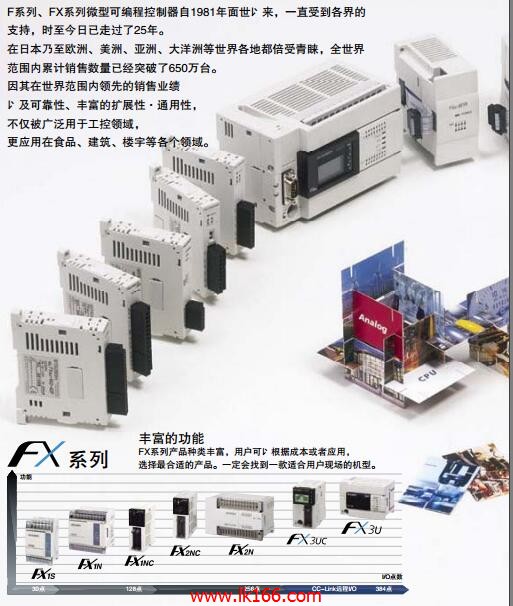
Station type: Master station.
Maximum nu
MITSUBISHI
PLC
FX3U-128MT/ESS
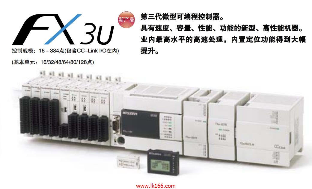
Max input / output points: 128 points.
S
MITSUBISHI
PLC
FX3S-30MT/ESS-2AD
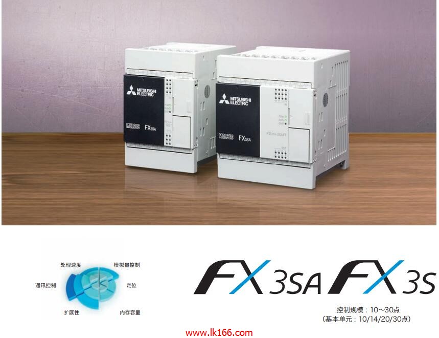
Built in analog input models.
Input / ou
MITSUBISHI
PLC
FX3U-64MT/ESS
Max input / output points: 64 points.
Su

