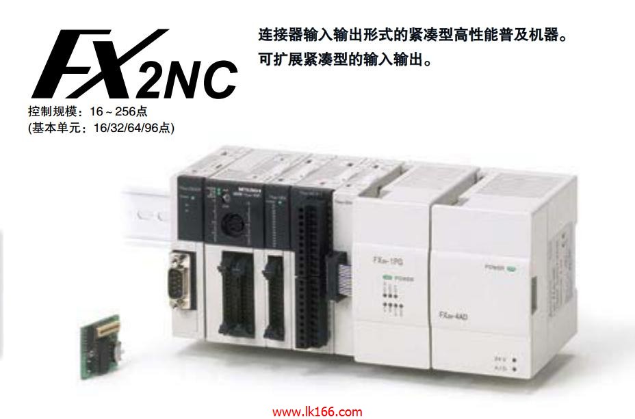
FX2NC-16MT-DSS
- Brand: MITSUBISHI
- Country: JAPAN
- Name: PLC
- Model: FX2NC-16MT-DSS
- Price: 0 >
MITSUBISHI FX2NC-16MT-DSS
The length of the line: 5m.
IP level: IP67.
Bending life: standard.
Encoder cable for HF-KP/HF-MP/HF-SP/HF-JP/HC-LP/HC-UP series. Input points: 36 points.
Output points: 24 points.
Power supply voltage: AC240-360V.
Output type: transistor output (source).
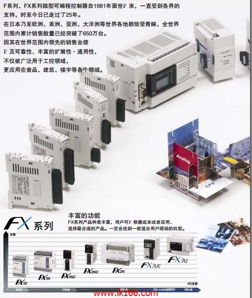
Built in CPU, power supply, input and output . While maintaining the convenience of FX1N while improving performance FX2NC-16MT-DSS.
Special adaptor and function expansion board can be installed and used FX3 series FX2NC-16MT-DSS
High speed operation.
Basic instructions: 0.21 s/ instruction.
Application instruction: 0.5 s/ instruction.
Large capacity memory.
Built in program memory 32000 steps.
EEPROM memory cartridge with program transfer function FX2NC-16MT-DSS. Protective film for 8 . 4 inch screen.
Transparent, 5.
Applicable model: GT12. Program 2 channel connection, AnCPU/QnACPU use.
MITSUBISHI PLC detection, fault diagnosis and display and other procedures.
These procedures are relatively independent, generally in the basic completion of the program design and then add.
MITSUBISHI PLC protection and chain procedures.
Protection and chain is an indispensable part of the program, must be carefully considered FX2NC-16MT-DSS.
It can avoid the control logic confusion caused by illegal operations. Input and output points: 1024 points.
Input / output data points: 8192 points.
Program capacity: 60k.
Basic command processing speed (LD command) S:0.2.
The length of time required to execute the instruction, the length of the user''s program, the type of instruction, and the speed of the CPU execution are very significant,
Generally, a scanning process, the fault diagnosis time,
Communication time, input sampling and output refresh time is less,
The execution time is accounted for the vast majority of.
The photoelectric coupler is composed of two luminous two extreme tubes and a photoelectric transistor.
Light emitting diode two: the input of a photo coupler and the change of electrical signal,
The light signal is generated by the light emitting diode, which is the same as the input signal.
The working process of the input interface circuit: when the switch is closed, the diode light,
The transistor is then guided to the internal circuit and input signal under the irradiation of the light.
When the switch is off, the diode does not emit light, and the transistor is not on the way. Internal circuit input signal.
It is through the input interface circuit to the external switch signal into PLC internal can accept the digital signal.
Photoelectric three levels: in the light of the light signal conduction, the degree of light signal and the intensity of the light signal.
The output signal has a linear relationship with the input signal in the linear operating region of the photoelectric coupler.
Useer program storage cappacity: it is a measure of how much the user application can store the number of indicators FX2NC-16MT-DSS.
Usually in words or K words as units. 16 bit binary number is a word,
Every 1024 words are 1K words. PLC to store instructions and data in words.
General lloggical operation instructions each account for 1 words FX2NC-16MT-DSS. Timer / counter,
Shift instruction accounted for 2 words. Data operation instructions for 2~4.
FX2NC-16MT-DSS Operation manual/Instructions/Model selection sample download link: /searchDownload.html?Search=FX2NC-16MT-DSS&select=5
...more relevant model market price >>>>
Related products
MITSUBISHI
Input module
FX2NC-16EX
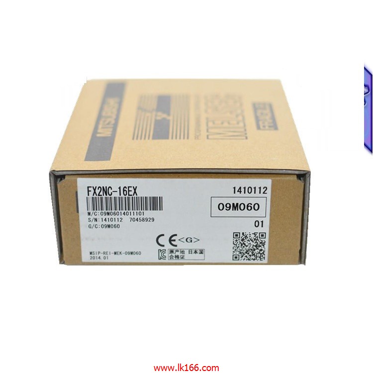
Function: no terminal input.
Input point
MITSUBISHI
PLC
FX2N-16MT-DSS
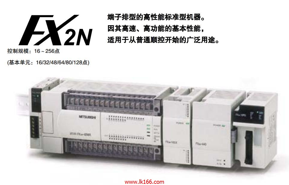
Max input / output points: 16 points.
Po
MITSUBISHI
output module
FX2NC-16EYT
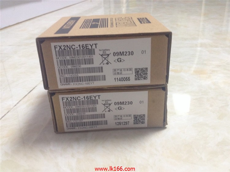
Output points: 16 points.
Output form: t
MITSUBISHI
Extension module
FX2NC-16EX-T-DS
Input points: 16 points.
Power supply: t

