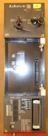
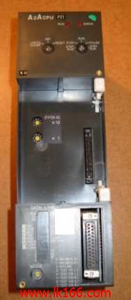
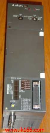
A2ACPUP21-S4
- Brand: MITSUBISHI
- Country: JAPAN
- Name: CPU unit
- Model: A2ACPUP21-S4
- Price: 0 >
MITSUBISHI A2ACPUP21-S4
Fast connector type.
Voltage input.
Number of channels: 8 channels.
Occupied the number of stations: Ver.1 mode occupied 3 stations, Ver.2 mode occupied 1 stations.
Station type: remote equipment station.
MITSUBISHI PLC hardware implementation
Hardware implementation is mainly for the control cabinet and other hardware design and field construction A2ACPUP21-S4.
Design control cabinet and the operating table and other parts of the electrical wiring diagram and wiring diagram A2ACPUP21-S4
Electrical interconnection diagram of each part of the design system.
According to the construction drawings of the site wiring, and carry out a detailed inspection.
Because the program design and hardware implementation can be carried out at the same time,
So the design cycle of the MITSUBISHI PLC control system can be greatly reduced A2ACPUP21-S4.
MITSUBISHI PLC online debugging.
On-line debugging is the process that will through the simulation debugging to further carry on the on-line unification to adjust.
On-line debugging process should be step by step,
From MITSUBISHI PLC only connected to the input device, and then connect the output device, and then connect to the actual load and so on and so on step by step A2ACPUP21-S4.
If you do not meet the requirements, the hardware and procedures for adjustment.
Usually only need to modify the part of the program can be. "Input points: 32 points.
Rated input voltage and frequency: DC24V.
Rated input current: TYP 4.0mA.
Response time: 0.1 ~ 70ms.
Common way: 32 point / public end.
Interrupt function: have.
External wiring connection mode: 40 pin connector.
The input and output module is the interface between the switch, sensor, actuator, and other control system of the ON/OFF signal processing.
Compared with the previous series, iQ-R MELSEC series of input and output modules have more features,
1 modules can be used for a variety of purposes, to help reduce the cost of deployment and maintenance costs.
The module design of the pursuit of convenience".
Paste the white label on the input module and paste the red label on the output module,
The rated specifications are clearly marked on the front of the module, which can prevent the use of errors.
The input and output number stamped on the top of the front dispplay input and output moodule LED, can easily confirm the status of the ON/OFF A2ACPUP21-S4.
The terminal arrangement of each signal is recorded on the wiring terminal of the 16 point module, and the false wiring can be prevented.
The 64 point module can be 32 points as the unit, throouggh the switch to switch to display the input and output number A2ACPUP21-S4.
In addition, serial number tag in the front of the module, can be easily recognized. "
A2ACPUP21-S4 Operation manual/Instructions/Model selection sample download link: /searchDownload.html?Search=A2ACPUP21-S4&select=5
...more relevant model market price >>>>
Related products
MITSUBISHI
CPU unit
A2ACPUR21-S1

Input and output points: 1024 points.
In
MITSUBISHI
CPU unit
A2ACPUP21-S4

Input and output points: 1024 points.
In
MITSUBISHI
CPU unit
A2ACPUP21

Input and output points: 512 points.
Inp
MITSUBISHI
CPU unit
A2ACPUR21

Input and output points: 512 points.
Inp


