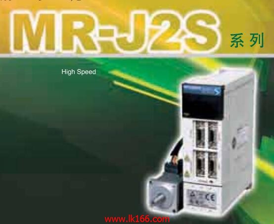
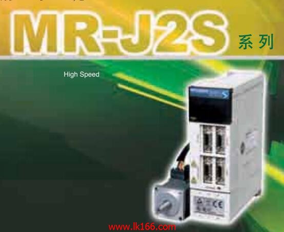
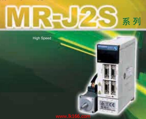
MR-J2S-10CP-S084
- Brand: MITSUBISHI
- Country: JAPAN
- Name: Built in positioning function servo amplifier
- Model: MR-J2S-10CP-S084
- Price: 0 >
MITSUBISHI MR-J2S-10CP-S084
Motor: HA-LH type.
Power: 7.0kw.
Speed: 2000r/min.
According to the types of power supply: can be divided into DC motor and AC motor.
The structure and working principle of DC motor can be divided into four parts: brushless DC motor and brushless DC motor.
Brushless DC motor can be divided into: permanent magnet DC motor and DC motor .
DC Motor Division: Series DC motor, DC motor, DC motor and DC motor MR-J2S-10CP-S084
Permanent magnet DC Motor Division: rare earth permanent magnet DC motor, ferrite permanent magnet DC motor and aluminum nickel Gu Yongci DC motor. Cable length: 6CM.
For functional connectivity (horizontal extension) GOT (D-sub 25 male and) RS422 cable pins: (D-sub 25 female pins:) connection MR-J2S-10CP-S084. Drive: MR-H_ACN series CC-LINK features.
Rated output: 22KW.
The test system is composed of two parts, namely, the servo driver, the motor system and the host computer.
The host computer sends the speed command signal to the servo driver,
Servo drives start to run in accordance with the instructions.
In the course of operation, the running data of the servo system is collected by the host computer and the data acquisition circuit,
And carries on the preservation, the analysis and the display to the data MR-J2S-10CP-S084. Because the motor is not loaded in this test system,
So compared with the previous two kinds of testing systems, the system has a relatively small volume,
And the measurement and control circuit of the system is relatively simple,
But it also makes the system can not simulate the actual operation of the servo drive.
Usually, such testing system is only used to test the rotational speed and angular displacement of the tested system under no-load condition,
And can not carry on the comprehensive and accurate test to the servo drive. 8 slots.
Power supply unit.
QnAS series unit installation.
High speed access.
CE logo fit.
I/O points is an important indicator of PLC.
Reasonable selection of I/O points can not only satisfy the control requirements of the system,
And the total investment of the system is the lowest.
The input and output points and types of PLC should be determined according to the analog quantity and switch quantity of the controlled object,
Generally an input / output element to take up an input / output point.
Taking into account the future adjustment and expansion,
In general should be estimated on the total number of points plus the amount of spare 20%~30%.
When the programmer input programinto the user program memory,
Then CPU according to the function of the system (the system program memory to explain the compiler),
Translate the user program into PLC internally recognized by the user to compile the program.
Relay output interface circuit of PLC
Working process: when the internal circuit output digital signal 1,
There is a current flowing through, the relay coil has a current, and then the normally open contact is closed,
Provide load current and voltage MR-J2S-10CP-S084.
When the internal circuit outputs a digital signal 0, there is no current flowing through it,
The relay coil does not have a current, and the normally open contact is broken off,
A current or voltage that is discoonnnected from the load MR-J2S-10CP-S084.
It is through the output interface circuit to the internal digital circuit into a signal to make the load action or not action.
MR-J2S-10CP-S084 Operation manual/Instructions/Model selection sample download link: /searchDownload.html?Search=MR-J2S-10CP-S084&select=5
...more relevant model market price >>>>
Related products
MITSUBISHI
Universal interface servo amplifier
MR-J2S-10A

MITSUBISHI general purpose AC servo ampl
MITSUBISHI
Universal interface servo amplifier
MR-J2S-15KA4

MITSUBISHI general purpose AC servo ampl
MITSUBISHI
Built in program type operational function servo amplifier
MR-J2S-10CL1

MITSUBISHI general purpose AC servo ampl
MITSUBISHI
SSCNET interface servo amplifier
MR-J2S-15KB

MITSUBISHI general purpose AC servo ampl

