A0J2E-E28AR
- Brand: MITSUBISHI
- Country: JAPAN
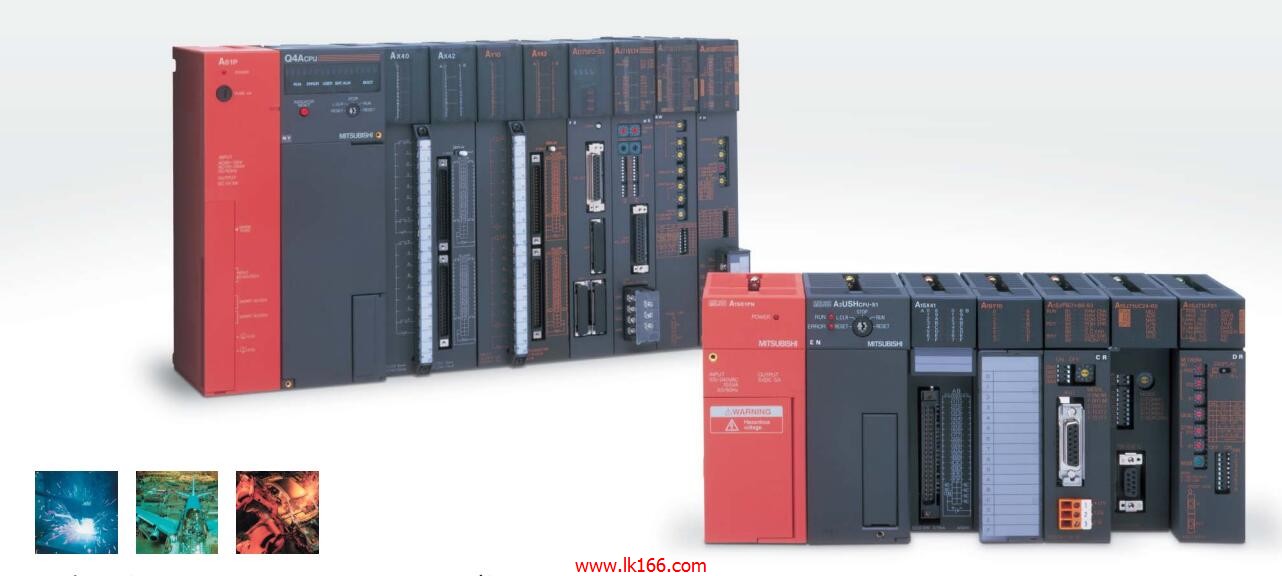
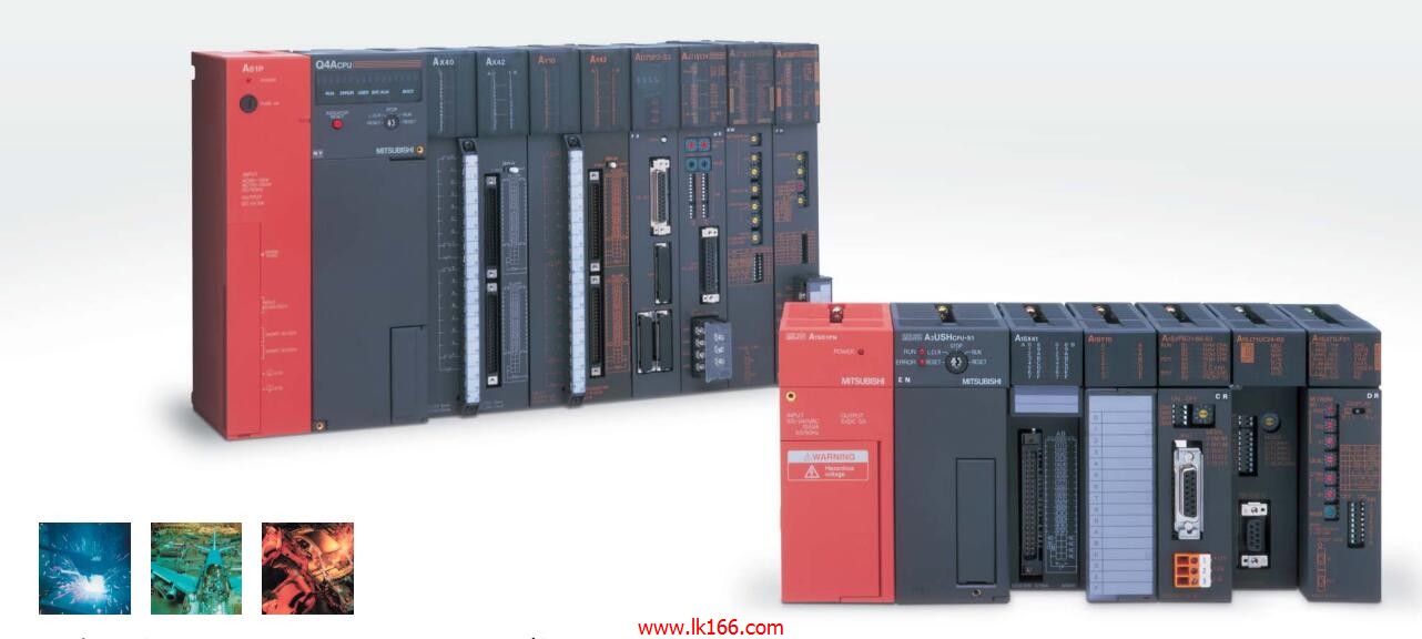
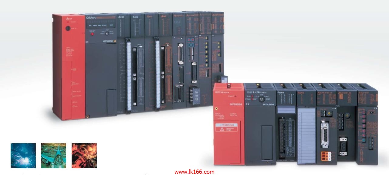
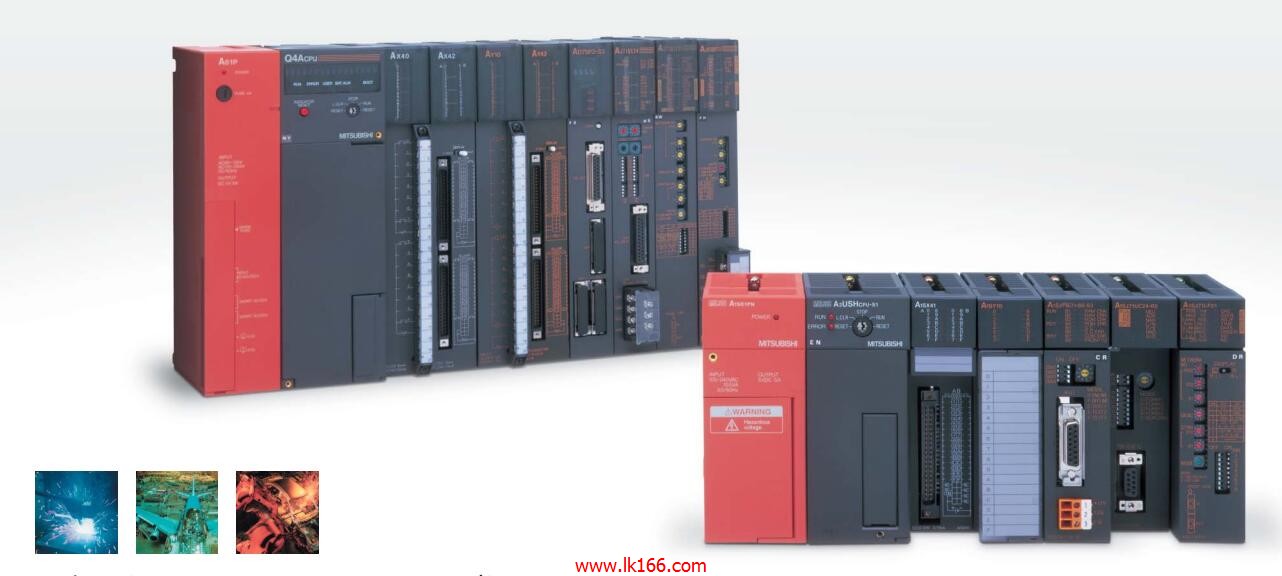
- Name: Extension module
- Model: A0J2E-E28AR
- Price: 0 >
MITSUBISHI A0J2E-E28AR
According to the control requirements of the system, using the appropriate design method to design MITSUBISHI PLC program.
Procedures to meet the requirements of system control as the main line,
Write one by one to achieve the control function or the sub task of the program,
Gradually improve the functions specified by the system .
MITSUBISHI PLC initialization procedure A0J2E-E28AR. After MITSUBISHI PLC on power, the general need to do some of the initial operation,
In order to start making necessary preparations, to avoid the wrong operation of the system A0J2E-E28AR
The main contents of the initialization program are: to some data area, counter and so on,
Data needed to restore some of the data area,
Set or reset some relays,
For some initial state display, etc A0J2E-E28AR. . "Connecting cable for handheld GOT and PLC.
Cable length: 10 meters.
Application: RS-422 connection and RS-232C connection. For video input (NTSC/PAL) 4ch.
Applicable model: GT27. "MITSUBISHI inverter FR-E720S series.
Voltage level: single phase 200V.
Frequency converter capacity: 0.1KW.
The use of frequency converter motor is in order to speed, and reduce the starting current A0J2E-E28AR.
In order to produce a variable voltage and frequency, the device is the first power of the AC power conversion to DC (DC), the process is called rectification.
The direct current (DC) is transformed into alternating current (AC) and its scientific term is "inverter" (inverter).
General inverter is the DC power supply inverter for a certain fixed frequency and a certain voltage of the inverter.
For the inverter as the frequency adjustable, adjustable voltage inverter, we called the inverter.
Inverter output waveform is simulated sine wave, mainly used in three-phase asynchronous motor speed control, and also called frequency governor. "Cable length: 30m.
For MR-J2S-700A (4) /CP/CL or less.
Encoder for HC-SFS; HC-LFS; HC-RFS; 2000r/min HA-LFS; HC-UFS servo motor.
-L represents bending life.
Output points: 4 points.
Output voltage and current: DC12/24V.
Output response time: 2ms.
4 point /1 a public side.
Output form: transistor output, leakage type.
16 point terminal station.
MITSUBISHI PLC protection and chain procedures.
Protection and chain is an indispensable part of the program, must be carefully considered.
It can avoid the control logic confusion caused by illegal operations.
MITSUBISHI PLC initialization procedure. After MITSUBISHI PLC on power, the general need to do some of the initial operation,
In order to start making necessary preparations, to avoid the wrong operation of the system.
The main contents of the initialization program are: to some data area, counter and so on,
Data needed to restore some of the data area,
Set or reset some relays,
For some initial statte display, etc A0J2E-E28AR..
MITSUBIISHI PLC program simulation debugging
The basic idea of program simulation debugging is,
In order to facilitate the form of simulation to generate the actual state of the scene,
Create the necessary environmental conditions for the operation of thee prrogram A0J2E-E28AR.
Depending on the way the field signals are generated,
The simulation debugging has two forms of hardware simulation and software simulation.
A0J2E-E28AR Operation manual/Instructions/Model selection sample download link: /searchDownload.html?Search=A0J2E-E28AR&select=5
...more relevant model market price >>>>


