 LK Automation Limited
MITSUBISHI AY42-S1 datasheet PDF
Product model: AY42-S1
Name: Transistor output module
Brand: MITSUBISHI
Sort: PDF datasheet
File language: English
Download link: MITSUBISHI AY42-S1 PDF datasheet
Master / local station.
QnACPU use.
According to the control requirements of the system, using the appropriate design method to design MITSUBISHI PLC program.
Procedures to meet the requirements of system control as the main line,
Write one by one to achieve the control function or the sub task of the program,
Gradually improve the functions specified by the system AY42-S1 PDF.
MITSUBISHI PLC initialization procedure AY42-S1 After MITSUBISHI PLC on power, the general need to do some of the initial operation,
In order to start making necessary preparations, to avoid the wrong operation of the system.
The main contents of the initialization program are: to some data area, counter and so on,
Data needed to restore some of the data area,
Set or reset some relays,
For some initial state display, etc AY42-S1 PDF. . "Cable length: 20.6 meters.
Small CPU long distance connecting cable.
For QnAS/AnSCPU/ motion control and GOT connection.
For connection between A7GT-CNB and GOT.
Combination A8GT-EXCNB and A8GT-C_BS. Special multi axis positioning controller for NSD servo system.
Coaxial data communication line function.
Program capacity: Max 60K step AY42-S1 PDF.
Input / output points: 1920 points.
The number of I/O thyristor DC motor control required tube DC motor speed control system is the main form of DC speed regulation,
The thyristor rectifier unit is used to supply power to the DC motor.
PLC control of the DC drive system, the input of the PLC in addition to the main signal outside the signal,
We need to consider the switching signal, the fault signal transmission device, brake signal and fan fault signal.
The output of the PLC mainly consider the speed command signal positive 1~3 level, 1~3 level, allowing reverse switching signal and brake open signal etc..
In general, a reversible DC drive system controlled by PLC is approximately 12 input points and 8 output points,
An irreversible DC drive system requires 9 inputs and 6 output points. Enter 16 points: 24VDC.
Response time 1.5ms.
Waterproof type.
4 wire type.
Waterproof connector type.
MITSUBISHI PLC hardware implementation
Hardware implementation is mainly for the control cabinet and other hardware design and field construction.
Design control cabinet and the operating table and other parts of the electrical wiring diagram and wiring diagram.
Electrical interconnection diagram of each part of the design system.
According to the construction drawings of the site wiring, and carry out a detailed inspection.
Because the program design and hardware implementation can be carried out at the same time,
So the design cycle of the MITSUBISHI PLC control system can be greatly reduced.
MITSUBISHI PLC online debugging.
On-line debugging is the process that will through the simulation debugging to further carry on the on--line unification to adjust AY42-S1 datasheet.
On-line debugging process should be step by step,
From MITSUBISHI PLC only connected to the input device, and then connect the output device, and then connect to the actual load and so on and so on stepp by step AY42-S1 datasheet.
If you do not meet the requirements, the hardware and procedures for adjustment.
Usually only need to modify the part of the program can be.
Related products
MITSUBISHI
CPU unit
A2ACPUP21-S1
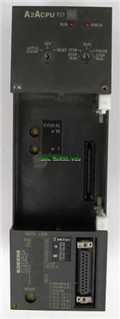
Input and output points: 1024 points.
In
MITSUBISHI
CPU unit
A2ACPUR21-S1
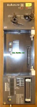
Input and output points: 1024 points.
In
MITSUBISHI
CPU unit
A2NCPUP21-S1
Input and output points: 1024 points.
In
MITSUBISHI
CPU unit
A2UCPU-S1
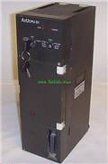
Input and output points: 1024 points.
In


