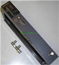
MITSUBISHI AJ71QC24 datasheet PDF
Product model: AJ71QC24
Name: Serial communication module
Brand: MITSUBISHI
Sort: PDF datasheet
File language: English
Download link: MITSUBISHI AJ71QC24 PDF datasheet
A set of 5 (LOGO removable, man-machine interface provides one).
Applicable model: A95_GOT (-M3). Input type: DC input, positive public end / negative public end.
Input points: 32 points.
Enter the response time: 1.5ms the following.
Rated input voltage / current: DC24V/5mA.
External connection: 1 wire AJ71QC24 PDF.
40 pin connector type (FCN connector type).
Through the 40 pin connector type (FCN connector type) can be connected to a variety of devices AJ71QC24
Can be installed along the 6 direction.
MITSUBISHI PLC program simulation debugging
The basic idea of program simulation debugging is,
In order to facilitate the form of simulation to generate the actual state of the scene,
Create the necessary environmental conditions for the operation of the program AJ71QC24 PDF.
Depending on the way the field signals are generated,
The simulation debugging has two forms of hardware simulation and software simulation. Cable length: 0.055 meters.
Extending cable to connect CPU main substrate and extended substrate,
According to the model can provide different cable length,
If you need to connect the AnN type expansion substrate is required,
Selection of A1SC05NB (A1SC07NB) cable AJ71QC24 PDF. JEMANET (OPCN-1) interface unit from the station.
The response time of PLC is the interval between the time of the change of the external output signal of the PLC and the time of the change of the external output signal which is controlled by it,
Lag time, this is the time constant of the input circuit,
The time constant of the output circuit, the arrangement of the user statement and the use of the instruction,
The cycle scan mode of PLC and the way of PLC to refresh the I/O and so on.
This phenomenon iis called the I/O delay time effect AJ71QC24 datasheet.
Input status and input information input from the input interface,
CPU will be stored in the working data memory or in the input image register.
And then combine the data and the program with CCPU AJ71QC24 datasheet.
The result is stored in the output image register or the working data memory,
And then output to the output interface, control the external drive.
Related products
MITSUBISHI
Coaxial cable module
AJ71QLR21

3C-2V/5C-2V coaxial cale.
Doule loop.
MITSUBISHI
Ethernet module
AJ71QE71-B5

Ethernet network module 10BASE5
Control
MITSUBISHI
Network module
AJ71QE71N3-T

10BASE-T.
For Q mode.
When communicating
MITSUBISHI
Network module
AJ71E71N-B2

10BASE2.
When communicating in the PLC n


