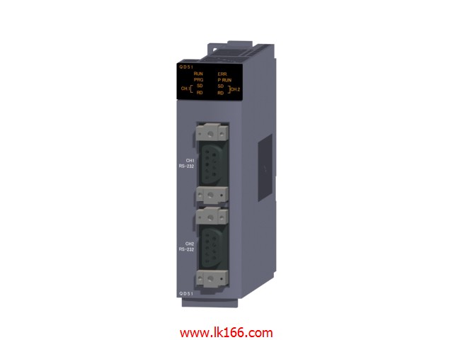
Input and output points: 512 points.
Input / output data points: 8192 points.
Program capacity: 28k.
Basic command processing speed (LD command) S:0.2.
The length of time required to execute the instruction, the length of the user''s program, the type of instruction, and the speed of the CPU execution are very significant,
Generally, a scanning process, the ffault diagnosis time,
Communication time, input sampling and output refresh time is less,
The execution time is accounted for the vast majority of QD51 QD51.
The photoelectric coupler is composed of two luminous two extreme tubes and a photoelectric transistor.
Light emitting diode two: the input of a photo coupler and the change of electrical signal,
The light signal is generated by the light emitting diode, which is the same as the input signal QD51.
The working process of the input interface circuit: when the switch is closed, the diode light,
The transistor is then guided to the internal circuit and input signal under the irradiation of the light.
When the switch is off, the diode does not emit light, and the transistor is not on the way MITSUBISHI QD51. Internal circuit input signal.
It is through the input interface circuit to the external switch signal into PLC internal can accept the digital signal.
Photoelectric three levels: in the light of the light signal conduction, the degree of light signal and the intensity of the light signal MITSUBISHI QD51.
The output signal has a linear relationship with the input signal in the linear operating region of the photoelectric coupler.
User program storage capacity: it is a measure of how much the user application can store the number of indicators.
Usually in words or K words as units MITSUBISHI QD51. 16 bit binary number is a word,
Every 1024 words are 1K words. PLC to store instructions and data in words.
General logical operation instructions each account for 1 words. Timer / counter,
Shift instruction accounted for 2 words. Data operation instructions for 2~4.
Input: 2 channels.
Input: thermocouple / micro voltage / voltage / current.
Conversion speed (input):25ms/2 channel.
Sampling period: 25ms/2 channel.
Output: DC4~20mA.
Conversion speed (output):25ms/2 channel.
18 point terminal station.
With 5 kinds of PID control mode.
Loop control module suitable for fast response object control, such as temperature control, flow control, etc..
The loop control module has a PID control format and a sampling period of 25ms that is proportional to the speed,
Support high precision, high resolution Thermocouple Input, micro voltage input, voltage input, current input and current output.
The most suitable for high speed lift and temperature control and pressure control, flow control and other requirements of the application of high speed response.
Can be connected with JIS, IEC, NBS, ASTM standard thermocouple.
Through the small voltage, voltage, current input sensor, can be measured in a variety of input range of analog.
Provides the program control function, can according to the specific requirements of the time automatically change the target value (SV) and PID constant [proportional band (P), integration time (I), differential time (D)],
And cascade control function, allowing channel 1 as the main station, channel 2 for the control from the station.
BASIC program execution module.
RS-232.
2 channel.
Ultra high speed processing, production time is shortened, better performance.
As applications become larger and more complex, it is necessary to shorten the system operation cycle time.
The operation period can be shortened by the super high basic operation speed 1.9ns.
In addition to achieve in the past with the control of single-chip high-speed control,
The system performance can be improved by reducing the total scan time,
To prevent any possible performance bias.
The position signal of the first axis servo amplifier, which is useed on the motion CPU, is used as a trigger,
Starting from the programmable controller CPU to the second axis servo amplifier,
Time to output speed command of servo amplifier QD51.
This time is the index of data transmission speed between CPU.
