 LK Automation Limited
DC24V transistor output module for 40 pin connector (drain type).A0J2 56.
Input / output unit 2
MITSUBISHI PLC program simulation debugging
The basic idea of program simulation debugging is,
In order to facilitate the form of simulation to generate the actual state of the scene,
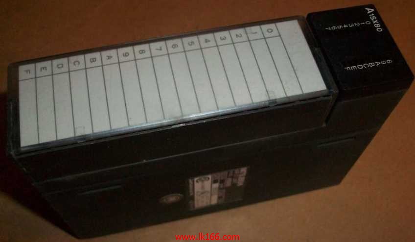
Create the necessary environmental conditions for the operation of the program A1SX80.<
Depending on the way the field signals are generated,
The simulation debugging has two forms of hardware simulation and software simulation A1SX80.
Type of input: DC source.
Input points: 16 points.
Input voltage: 12/24DC.
Input current: 3/7mA.
Connection mode: terminal row.
Common common point: 32.
Functional block diagram language is a kind of PLC programming language, which is similar to digital logic circuit A1SX80.
The function module is used to represent the function of the module,
Different function modules have different functions.
Functional module figure programming language features: functional block diagram programming language is characterized by a functional module for the unit,
Analysis and understanding of the control scheme is simple and easy: function module is to use graphical form of expression,
Intuitive, for a digital logic circuit based on the design of the staff is very easy to master the programming;
Control system with complex scale and complex control logic,
Because the function module diagram can clearly express the function relation, the programming debugging time is greatly reduced MITSUBISHI A1SX80 MITSUBISHI A1SX80. QCPU (Q mode) bus connection.
1 joint.
Applicable models: A985 (-V) /975/970/960GOT. Input voltage range: DC24V.
Output voltage: DC5V MITSUBISHI A1SX80.
Output current: 8A.
PLC selection with the development of PLC technology, more and more types of PLC products,
Function is becoming more and more perfect, and its application is more and more extensive.
Different series of different models of PLC has different performance, applicable occasions also have different emphasis,
Price also has a greater difference. Therefore PLC selection,
Under the premise of meeting the control requirements,
Should consider the best performance to price ratio, a reasonable choice of PLC. 32: terminal line adapter 0.3mm2 (AGW22).GI fiber optic cable.
Dual loop for Q mode.
Remote I/O network (remote control station).
How to choose MITSUBISHI PLC.
MITSUBISHI PLC options include the choice of MITSUBISHI PLC models, capacity, I/O module, power, etc..
MITSUBISHI PLC distribution I/O points and design MITSUBISHI PLC peripheral hardware circuit
Draw the I/O point of the PLC and the input / output device connection diagram or the corresponding table,
This part also can be carried out in second steps.
Design PLC peripheral hardware circuit.
Draw the electrical wiring diagram of the other parts of the system,
Including the main circuit and the control circuit does not enter the PLC, etc A1SX80..
The electrical schematic diagram of the system composed of I/O PLC connection diagram and PLC peripheral electrical circuit diagram.
So far the system''s hardware electrical circuit has been determined.


