 LK Automation Limited
3C-2V/5C-2V coaxial cable.
Double loop.
Remote station.
According to the control requirements of the system, using the appropriate design method to design MITSUBISHI PLC program.
Procedures to meet the requirements of system control as the main line,
Write one by one to achieve the control function or the sub task of the program,
Gradually improve thhe functions specified by the system AJ65SBTB1-8T1.
MITSUBISHI PLC initialization procedure. After MITSUBISHI PLC on power, the general need to do some of the initial operation,
In order to start making necessary preparations, to avoid the wrong operation of the system AJ65SBTB1-8T1.
The main contents of the initialization program are: to some data area, counter and so on,
Data needed to restore some of the data area,
Set or reset some relays,
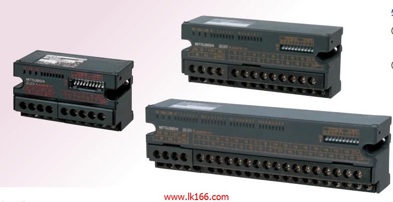
For some initial state display, etc AJ65SBTB1-8T1.. External input / output interface unit
Output type: transistor output, drain type.
Output points: 8 points.
OFF leakage current: 0.1mA.
Output protection function: No.
Rated load voltage / current: DC12V/DC24V/0.5A.
External connection: 1 wire MITSUBISHI AJ65SBTB1-8T1.
According to the external connection mode and the external equipment input and output specifications,
Choose from a rich product lineup.
Finger protection through the upper part of the terminal,
The human body will not be exposed to live parts,
Therefore, the terminal station type remote I/O module can be directly mounted to the machine tool MITSUBISHI AJ65SBTB1-8T1. Self service (IN, OUT): SI optical cable.
Other aspects (IN, OUT): SI optical cable.
Data link anomaly Bureau bypass.
Inter agency extension.
Cable transformation. RS-232 2 channel MITSUBISHI AJ65SBTB1-8T1.
Transfer speed: 2 channels.
A total of 115.2kbps.
Input status and input information input from the input interface,
CPU will be stored in the working data memory or in the input image register.
And then combine the data and the program with CPU.
The result is stored in the output image register or the working data memory,
And then output to the output interface, control the external drive.
Semiconductor circuit with memory function.
System program memory and user memory.
System program memory for storing system proggram,
Including management procedures, monitoring procedures, as well as the user program to do the compiler to compile the process of interpretation AJ65SBTB1-8T1.
Read only memory. Manufacturers use, content can not be changed, power does not disappear.