 LK Automation Limited
MITSUBISHI AY70 datasheet PDF
Product model: AY70
Name: CMOS TTL output module
Brand: MITSUBISHI
Sort: PDF datasheet
File language: English
Download link: MITSUBISHI AY70 PDF datasheet
QnA/ACPU bus connection.
1 joint.
Applicable models: A985 (-V) /975/970/960GOT. Capable of continuous thermocouple or platinum temperature measurement.
In addition, the temperature measurement range can be set with the use of the temperature.
The length of time required to execute the instruction, the length of the user''s program, the type of instruction, and the speed of the CPU execution are very significant,
Generally, a scanning process, the fault diagnosis time,
Communication time, input sampling and output refresh time is less,
The execution time is accounted for the vast majority of AY70 PDF AY70
The response time of PLC is the interval between the time of the change of the external output signal of the PLC and the time of the change of the external output signal which is controlled by it,
Lag time, this is the time constant of the input circuit,
The time constant of the output circuit, the arrangement of the user statement and the use of the instruction,
The cycle scan mode of PLC and the way of PLC to refresh the I/O and so on AY70 PDF.
This phenomenon is called the I/O delay time effect. For A6TBXY36/A6TBXY54/A6TBX70E (common cathode; drain type) long 5m AY70 PDF. For common cathode input module and leaky type output module (2 line type).RS-232 1 channels.
With DC input 2 points.
Transistor output 2.
Number of stations: 1 stops.
Station type: intelligent equipment station.
MITSUBISHI PLC online debugging.
On-line debugging is the process that will through the simulation debugging to further carry on the on-line unification to adjust.
On-line debugging process should be step by step,
From MITSUBISHI PLC only connected to the input device, and then connect the output device, and then connect to the actual load and so on and so on step by step.
If you do not meet the requirements, the hardware and procedures for adjustment.
Usually only need to modify the part of the program can be.
MITSUBISHI PLC hardware implementation
Hardware implementation is mainly for the control cabinet and other hardware design and field construction.
Design control cabinet and the operating table and other parts of the eelectrical wiring diagram and wiring diagram AY70 datasheet.
Electrical interconnection diagram of each part of the design system.
According to the construction drawings of the site wiring, and carry out a detailed inspection.
Because the program deesign and hardware implementation can be carried out at the same time,
So the design cycle of the MITSUBISHI PLC control system can be greatly reduced AY70 datasheet.
Related products
MITSUBISHI
Transistor output module
AY40A
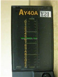
Output points: 16 points.
Voltage: DC12/
MITSUBISHI
Relay output module
AY11
Output points: 16 points.
Voltage: DC24V
MITSUBISHI
Transistor output module
AY81
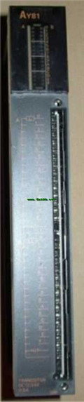
Output points: 32 points.
Voltage: DC12/
MITSUBISHI
Relay output module
AY15CEU
Output points: 24 points.
Voltage: DC24V


