 LK Automation Limited
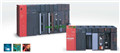
MITSUBISHI AJ71QC24N datasheet PDF
Product model: AJ71QC24N
Name: Serial communication module
Brand: MITSUBISHI
Sort: PDF datasheet
File language: English
Download link: MITSUBISHI AJ71QC24N PDF datasheet
DC input points: 4 points.
Input voltage and current: 7mA, DC24V.
Input response time: 10ms.
4 point /1 a public side.
Positive / negative sharing.
Output points: 4 points.
Output voltage and current: DC24V/AC240V, 2A/1 point, 8A/1 common end.
Output response time: 12ms.
4 point /1 a public side.
Output form: relay AJ71QC24N PDF.
24 point terminal station.
MITSUBISHI PLC protection and chain procedures AJ71QC24N
Protection and chain is an indispensable part of the program, must be carefully considered.
It can avoid the control logic confusion caused by illegal operations.
MITSUBISHI PLC initialization procedure. After MITSUBISHI PLC on power, the general need to do some of the initial operation,
In order to start making necessary preparations, to avoid the wrong operation of the system AJ71QC24N PDF.
The main contents of the initialization program are: to some data area, counter and so on,
Data needed to restore some of the data area,
Set or reset some relays,
For some initial state display, etc..
MITSUBISHI PLC program simulation debugging
The basic idea of program simulation debugging is,
In order to facilitate the form of simulation to generate the actual state of the scene,
Create the necessary environmental conditions for the operation of the program AJ71QC24N PDF.
Depending on the way the field signals are generated,
The simulation debugging has two forms of hardware simulation and software simulation. G1-62.5/125 fiber optic cable.
Double loop.
PC inter network (management station / station) / remote I/O network (remote control station).
How to choose MITSUBISHI PLC.
MITSUBISHI PLC options include the choice of MITSUBISHI PLC models, capacity, I/O module, power, etc..
MITSUBISHI PLC distribution I/O points and design MITSUBISHI PLC peripheral hardware circuit
Draw the I/O point of the PLC and the input / output device connection diagram or the corresponding table,
This part also can be carried out in second steps.
Design PLC perripheral hardware circuit AJ71QC24N datasheet.
Draw the electrical wiring diagram of the other parts of the system,
Including the main circuit and the control circuit does not enter the PLC, etc..
The electrical schematic diagram of the system compoosed of I/O PLC connection diagram and PLC peripheral electrical circuit diagram AJ71QC24N datasheet.
So far the system''s hardware electrical circuit has been determined.
Related products
MITSUBISHI
GI fiber optic cable module
AJ71LP21G
G1-50/125 fier optic cale.
Doule loop
MITSUBISHI
MELSECNET/MINI-S3 module
AJ71PT32-S3
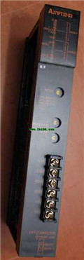
Fier optic cale / twisted pair cale.
MITSUBISHI
Ethernet module
AJ71QE71N-B2
10BASE2.
For Q mode.
Control layer /MELS
MITSUBISHI
Ethernet module
AJ71QE71-B5

Ethernet network module 10BASE5
Control