 LK Automation Limited
OMRON CS1W-CLK53 I/O Wiring Diagram PDF
Product model: CS1W-CLK53
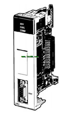
Name: controller link units
Brand: OMRON
Sort: I/O Wiring Diagram
File language: English
Download link: OMRON CS1W-CLK53 I/O Wiring Diagram
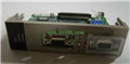
Name: CS1D CPU Unit for Single CPU Systems.
Specifications: Number of I/O points,
5,120 points (7 Racks);
Program capacity, 60 Ksteps;
Data Memory, 128 Kwords(DM: 32 Kwords,
EM: 32 Kwords×13 banks);
LD execution time, 0 CS1W-CLK53 PDF. 02 μs;
Duplex CPUs, --;
Interrupt functions, OK.
Current consumption: 5V system, 0.82A;
26V system, --.
Standards: UC1, N, L, CE.
Redundant CPU Units , Power Supply Units ,
Communications Units ,
and Expansion I/O Cables CS1W-CLK53 Name: Host Link Module.
Model: C200H-LK202-V1.
Communication ports: 1 RS-422.Name: e-CON Connectors.
Specifications: Inputs/Outputs;
8 inputs /8 outputs; PNP;
With Short-circuit and,
Disconnected Line Detection CS1W-CLK53 PDF.
"Easy" and "Flexible" system expansion,
with linked CC-Link and CompoNet.
Branching is easily made with CompoNet.
Wiring material cost can be reduced.
Bit-level I/O distribution reduces,
wiring in the system.
A wide variety of CompoNet Slave Units,
contribute to system size reduction CS1W-CLK53 PDF.
Seven-segment Display on the Gateway Unit,
helps to detect errors on site CS1W-CLK53 Manual.
The Participation Flags and Communications,
Error Flags can be checked at the Host,
Controller to detect the location and,
content of the error OMRON I/O Wiring Diagram. Product name: N@@S1- type CPU Units with 30 I/O Points.
Specifications: Power Supply, DC24V; Inputs, 18; Outputs, 12;
Output type: Transistor (sinking).
Program capacity: 8K steps.
memory Data capacity: 8K words.
External powersupply(24 VDC): --.
Current consumption: 5 V, 0.27A; 24 V,0.02A OMRON I/O Wiring Diagram.
Standards: CE.
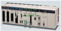
The CP1E Programmable Controller: Economical, Easy to use, and Efficient.
The E@@(S)-type Basic CPU Units provide cost,
performance and easy application with only basic functionality.
The N@@(S@) and NA-types Application CPU Units,
support Programmable Terminal connection, position control,
and inverter connection OMRON I/O Wiring Diagram. Name: Clamp Terminal Blocks.
Specifications: Outputs; 8 outputs ; PNP; --.
"Easy" and "Flexible" system expansion,
with linked CC-Link and CompoNet.
Branching is easily made with CompoNet.
Wiring material cost can be reduced CS1W-CLK53 I/O Wiring Diagram.
Bit-level I/O distribution reduces,
wiring in the system.
A wide variety of CompoNet Slave Units,
contribute to system size reduction.
Seven-segment Display on the Gateway Unit,
helps to detect errors on sitee CS1W-CLK53 Manual.
The Participation Flags and Communications,
Error Flags can be checked at the Host,
Controller to detect the location and,
content of the error.
Specifications: Number of I/O points,
5,120 points (7 Racks);
Program capacity, 60 Ksteps;
Data Memory, 128 Kwords(DM: 32 Kwords,
EM: 32 Kwords×13 banks);
LD execution time, 0 CS1W-CLK53 PDF. 02 μs;
Duplex CPUs, --;
Interrupt functions, OK.
Current consumption: 5V system, 0.82A;
26V system, --.
Standards: UC1, N, L, CE.
Redundant CPU Units , Power Supply Units ,
Communications Units ,
and Expansion I/O Cables CS1W-CLK53 Name: Host Link Module.
Model: C200H-LK202-V1.
Communication ports: 1 RS-422.Name: e-CON Connectors.
Specifications: Inputs/Outputs;
8 inputs /8 outputs; PNP;
With Short-circuit and,
Disconnected Line Detection CS1W-CLK53 PDF.
"Easy" and "Flexible" system expansion,
with linked CC-Link and CompoNet.
Branching is easily made with CompoNet.
Wiring material cost can be reduced.
Bit-level I/O distribution reduces,
wiring in the system.
A wide variety of CompoNet Slave Units,
contribute to system size reduction CS1W-CLK53 PDF.
Seven-segment Display on the Gateway Unit,
helps to detect errors on site CS1W-CLK53 Manual.
The Participation Flags and Communications,
Error Flags can be checked at the Host,
Controller to detect the location and,
content of the error OMRON I/O Wiring Diagram. Product name: N@@S1- type CPU Units with 30 I/O Points.
Specifications: Power Supply, DC24V; Inputs, 18; Outputs, 12;
Output type: Transistor (sinking).
Program capacity: 8K steps.
memory Data capacity: 8K words.
External powersupply(24 VDC): --.
Current consumption: 5 V, 0.27A; 24 V,0.02A OMRON I/O Wiring Diagram.
Standards: CE.
The CP1E Programmable Controller: Economical, Easy to use, and Efficient.
The E@@(S)-type Basic CPU Units provide cost,
performance and easy application with only basic functionality.
The N@@(S@) and NA-types Application CPU Units,
support Programmable Terminal connection, position control,
and inverter connection OMRON I/O Wiring Diagram. Name: Clamp Terminal Blocks.
Specifications: Outputs; 8 outputs ; PNP; --.
"Easy" and "Flexible" system expansion,
with linked CC-Link and CompoNet.
Branching is easily made with CompoNet.
Wiring material cost can be reduced CS1W-CLK53 I/O Wiring Diagram.
Bit-level I/O distribution reduces,
wiring in the system.
A wide variety of CompoNet Slave Units,
contribute to system size reduction.
Seven-segment Display on the Gateway Unit,
helps to detect errors on sitee CS1W-CLK53 Manual.
The Participation Flags and Communications,
Error Flags can be checked at the Host,
Controller to detect the location and,
content of the error.
Related products
OMRON
CS1W-SCB41-V1
Specifications: 1 × RS-232C port 1 × R
OMRON
DeviceNet Unit
CS1W-LCB01
Unit name: Loop Control Boards.
Specif
OMRON
Controller Link Units
CS1W-CLK13
Unit classifi cation: CS1 CPU Bus Unit.
OMRON
ID Sensor Unit
CS1W-V600C12

Unit type: CS1 Special I/O Units.
Conne


