 LK Automation Limited
MITSUBISHI MR-J3-15KT4 INSTRUCTION MANUAL (General-Purpose Interface) PDF
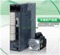
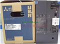
Product model: MR-J3-15KT4
Name: SERVO AMPLIFIER
Brand: MITSUBISHI
Sort: General-Purpose Interface INSTRUCTION MANUAL
File language: English
Download link: MITSUBISHI MR-J3-15KT4 INSTRUCTION MANUAL
Content: CNP2 connector two.
Purpose: MR-JE-200B to MR-JE-300B, MR-JE-200A to MR-JE-300A with. Superior high efficiency IPM motor.
Output power: 2.2kw MR-J3-15KT4 PDF.
Rated speed: 1500r/min.
Voltage level: 400V.
IPM motor MM-EFS series can not be used to run the power frequency power.
The total wiring length of the IPM motor shall not exceed 100m.
1 inverters can not connect multiple IPM motors at the same time MR-J3-15KT4 Drive: MR-H_AN series.
Rated output: 3.5KW.
Universal AC servo.
Servo driver (drives servo) also known as the "servo controller", "servo amplifier",
Is a kind of controller used to control the servo motor MR-J3-15KT4 PDF. Its function is similar to that of the frequency converter,
Belongs to a part of the servo system, which is mainly used in high precision positioning system.
In general, the servo motor is controlled by position, speed and torque in three ways,
To achieve high precision positioning of the transmission system, the current transmission technology is the high-end products MR-J3-15KT4 PDF.
Servo drive is an important part of modern motion control,
Is widely used in industrial robots and CNC machining centers and other automation equipment.
In particular, it has become a hot research topic in the field off servo drives for the control of AC permanent magnet synchronous motor MITSUBISHI INSTRUCTION MANUAL MR-J3-15KT4 Manual.
Current, speed and position 3 closed loop control algorithm based on vector control is widely used in AC servo drive system.
The speed closed-loop design of the algorithm is reasonable or not, for the entire servo control system,
Especially the speed control performance plays a key role MITSUBISHI INSTRUCTION MANUAL. Drive: MR-H_ACN series CC-LINK features.
Rated output: 0.2KW.
The test system is composed of two parts, namely, the servo driver, the motor system and the host computer.
The host computer sends the speed command signal to the servo driver,
Servo drives start to run in accordance with the instructions MITSUBISHI INSTRUCTION MANUAL.
In the course of operation, the running data of the servo system is collected by the host computer and the data acquisition circuit,
And carries on the preservation, the analysis and the display to the data. Because the motor is not loaded in this test system,
So compared with the previous two kinds of testing systems, the system has a relatively small volume,
Annd the measurement and control circuit of the system is relatively simple,
But it also makes the system can not simulate the actual operation of the servo drive MR-J3-15KT4 INSTRUCTION MANUAL.
Usually, such testing system is only used to test the rotational speeed and angular displacement of the tested system under no-load condition,
And can not carry on the comprehensive and accurate test to the servo drive MR-J3-15KT4 Manual.
Related products
MITSUBISHI
Full closed loop control driver
MR-J3-11KB4-RJ006
MITSUBISHI motor universal AC servo ampl
MITSUBISHI
CC-Link communication driver
MR-J3-100T

MITSUBISHI motor universal AC servo ampl
MITSUBISHI
Universal pulse interface driver
MR-J3-500A
MITSUBISHI motor universal AC servo ampl
MITSUBISHI
CC-Link communication driver
MR-J3-20T1

MITSUBISHI motor universal AC servo ampl


