 LK Automation Limited
MITSUBISHI AX41 User's Manual PDF
Product model: AX41
Name: I/O Module
Brand: MITSUBISHI
Sort: User's Manual
File language: English
Download link: MITSUBISHI AX41 User's Manual
Output points: 8 points.
Output voltage and current: DC12/24V.
Output response time: 2ms.
8 point /1 a public side.
Output form: transistor output, leakage type AX41 PDF.
24 point terminal station.
MITSUBISHI PLC protection and chain procedures.
Protection and chain is an indispensable part of the program, must be carefully considered.
It can avoid the control logic confusion caused by illegal operations AX41
MITSUBISHI PLC initialization procedure. After MITSUBISHI PLC on power, the general need to do some of the initial operation,
In order to start making necessary preparations, to avoid the wrong operation of the system AX41 PDF.
The main contents of the initialization program are: to some data area, counter and so on,
Data needed to restore some of the data area,
Set or reset some relays,
For some initial state display, etc..
MITSUBISHI PLC program simulation debugging
The basic idea of program simulation debugging is,
In order to facilitate the form of simulation to generate the actual state of the scene,
Create the necessary environmental conditions for the operation oof the program AX41 PDF AX41 Manual.
Depending on the way the field signals are generated,
The simulation debugging has two forms of hardware simulation and software simulation MITSUBISHI User's Manual. RS-232 1 channels.
With DC input 2 points.
Transistor output 2.
Number of stations: 1 stops.
Station type: intelligent equipment station.
MITSUBISHI PLC online debugging.
On-line debugging is the process that will through the simulation debugging to further carry on the on-line unification to adjust MITSUBISHI User's Manual.
On-line debugging process should be step by step,
From MITSUBISHI PLC only connected to the input device, and then connect the output device, and then connect to the actual load and so on and so on step by step.
If you do not meet the requirements, the hardware and procedures for adjustment MITSUBISHI User's Manual.
Usually only need to modify the part of the program can be.
MITSUBISHI PLC hardware implementation
Hardware implementation is mainly for the control cabinet and other hardware design and field construction.
Design control cabinet and the operating table and other parts of thhe electrical wiring diagram and wiring diagram AX41 User's Manual.
Electrical interconnection diagram of each part of the design system.
According to the construction drawings of the site wiring, and carry out a detailed inspection.
Because the program deesign and hardware implementation can be carried out at the same time,
So the design cycle of the MITSUBISHI PLC control system can be greatly reduced AX41 Manual.
Related products
MITSUBISHI
Input module
AX81-S2
Input points: 32 points.
Voltage: DC48/6
MITSUBISHI
AC input / relay output module
AX10Y10C
Input points: 16 points.
Input voltage a
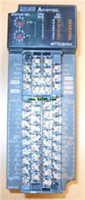
MITSUBISHI
Input module
AX71
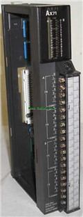
Input points: 32 points.
Voltage: DC5/12
MITSUBISHI
DC input / transistor output module
AX80Y80C
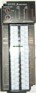
Input points: 16 points.
Input voltage a


