 LK Automation Limited
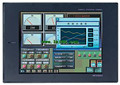
MITSUBISHI A975GOT-TBD-B User's Manual (Hardware) PDF
Product model: A975GOT-TBD-B
Name: Graphic Operation Terminal
Brand: MITSUBISHI
Sort: Hardware User's Manual
File language: English
Download link: MITSUBISHI A975GOT-TBD-B User's Manual
Liquid crystal display: 16 characters x 2 lines,
For data access (the state of operation of the central processor, device monitor / change). Cable length 10m; used in A6TE2-16SRN A975GOT-TBD-B PDF. Available network: Profibus-FMS.
Function: client or host.
The A1SJ71PB96F and A1SJ71PB92D modules allow a PLC ANS to connect to the Profibus system,
Meet the CE standard, using SWOIX/ProfiMap special programming software A975GOT-TBD-B
A1SJ71PB96F compatible with Profibus-FMS, as a master or client;
A1SJ71PB92D compatible with Profibus-DP, can be used as a master to control the remote Profibus-DP I/O. Analog channel: 16 channels A975GOT-TBD-B PDF.
Input / output (resolution): 0 ~ 4000.
Conversion speed: 100ms/16 channel.
Analog module installation.
Power supply: DC24V.
According to the control requirements of the system, using the appropriate design method to design MITSUBISHI PLC program.
Procedures to meet the requirements of system control as the main line,
Write one by one to achieve the control function or the sub task of the program,
Gradually improve the functions specified by the system A975GOT-TBD-B PDF.
MITSUBISHI PLC detection, fault diagnosis and display and other procedures.
These procedures are relatively independent, generally in the basic completion of the program design and then add MITSUBISHI User's Manual.
Hardware simulation method is to use a number of hardware equipment to simulate the generation of the signal,
The signals are connected to the input end of the PLC system in a hard wired way, and the timeliness is strong.
Software simulation method is in the MITSUBISHI PLC in the preparation of a set of simulation program,
The simulation provides the field signal, which is simple and easy to operate, but it is not easy to guarantee the timeliness MITSUBISHI User's Manual.
Simulation of the process of debugging, debugging method can be used to segment, and the monitoring function of programmer MITSUBISHI User's Manual. A pack of 20.
Applicable models:
AJ65FBTA - - - type. Input points: 32 points.
Input voltage and current: 3/7mA DC12/24V.
Input response time: 10ms.
16 point /1 a public side.
Positive pole sharing.
Output points: 24 points.
Output voltage: DC24V/AC240V, 2A/1 point, 5A/1 common end.
Output response time: 12ms.
Output type: relay output.
8 point /1 a public side.
With the surge absorber.
Control solenoid valve required I/O points by the action principle of the solenoid valve can be known,
A single coil soleenoid valve with PLC control to 2 input and 1 output,
A double coil solenoid valve requires 3 inputs and 2 outputs,
A button needs an input; a light sensitive switch needs 4 or 2 inputs,
A signal lamp needs 1 output, band switch,
Several bands are required for several inputs,
In general, a variety of position switches are required to take up 2 input points A975GOT-TBD-B Manual.
MITSUBISHI PLC is the main product in the production of MITSUBISHI motor in Dalian.
It uses a kind of programmable memory for its internal storage procedures,
Execute logic operation, sequence control, timing, counting and arithmetic operations, user oriented instruction,
And through digital or analog input / output control of various types of machinery or production process.
The number of I/O thyristor DC motor control required tube DC motor speed control system is the main form of DC speed regulation,
The thyristor rectifier unit is used to supply power to the DC motor.
PLC control of the DC drive system, the input of the PLC in addition to the main signal outside the signal,
We need to consider the switching signal, the fault signal transmission devicce, brake signal and fan fault signal A975GOT-TBD-B User's Manual.
The output of the PLC mainly consider the speed command signal positive 1~3 level, 1~3 level, allowing reverse switching signal and brake open signal etc..
In general, a reversible DC drivee system controlled by PLC is approximately 12 input points and 8 output points,
An irreversible DC drive system requires 9 inputs and 6 output points A975GOT-TBD-B Manual.
Related products
MITSUBISHI
10 inch man machine interface
A975GOT-TBA-EU
Series Name: A975GOT.
Size: 10 inches.
R
MITSUBISHI
10 inch man machine interface
A975GOT-TBA-B

Series Name: A975GOT.
Size: 10 inches.
R


