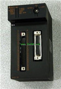
MITSUBISHI A1SY71 User's Manual PDF
Product model: A1SY71
Name: I/O Module
Brand: MITSUBISHI
Sort: User's Manual
File language: English
Download link: MITSUBISHI A1SY71 User's Manual
A pack of 10.
Applicable models:
AJ65VBTS - - - type.
AJ65VBTCE - - - type.
AJ65VBTCU - - - type.
AJ65ABTP - - - type.
AJ65VBCU- - type. RS-232 2 channel A1SY71 PDF.
Transfer speed: 0.3-19.2kbps.
Equipment layer / field bus CC-Link device layer is the PLC and other control devices and sensors and drive devices connected to the field network,
Network for the lowest layer of the whole network system A1SY71
Using CC-Link field bus connection, the number of wiring is greatly reduced,
Improve the maintainability of the system.
And, not just the amount of data ON/OFF and other switches,
Can also be connected to the ID system, bar code reader, inverter, man-machine interface and other intelligent devices,
From the completion of a variety of data communication,, the management of the terminal production information can be realized,
On the centralized management of the state of the machine movement,
Make maintenance work efficiency also greatly improved A1SY71 PDF A1SY71 PDF A1SY71 Manual.
Q series PLC in the use of CC-Link function better,
And easier to use. Cable length: 10.6 meters.
Small CPU long distance connecting cable.
For QnAS/AnSCPU/ motion control and GOT connection.
For connection between A7GT-CNB and GOT.
Combination A8GT-EXCNB and A8GT-C_BS MITSUBISHI User's Manual. RS-232:1, RS-422/485:1.
Transmission speed: 0.3 ~ 19.2kpbs.
Computer connection function.
Printer / peripheral device connection, BASIC language function.
How to choose MITSUBISHI PLC.
MITSUBISHI PLC options include the choice of MITSUBISHI PLC models, capacity, I/O module, power, etc MITSUBISHI User's Manual. .
MITSUBISHI PLC distribution I/O points and design MITSUBISHI PLC peripheral hardware circuit
Draw the I/O point of the PLC and the input / output device connection diagram or the corresponding table,
This part also can be carried out in second steps.
Design PLC peripheral hardware cirrcuit A1SY71 User's Manual.
Draw the electrical wiring diagram of the other parts of the system,
Including the main circuit and the control circuit does not enter the PLC, etc MITSUBISHI User's Manual. .
The electrical schematic diagram of the system compoosed of I/O PLC connection diagram and PLC peripheral electrical circuit diagram A1SY71 Manual.
So far the system''s hardware electrical circuit has been determined.
Related products
MITSUBISHI
Positioning module
A1SD71-S7

2 axes.
2 axis linear interpolation.
Con
MITSUBISHI
Terminal row adapter
A1STA32

The use of A1STA32 can significantly red
MITSUBISHI
DC source type input module
A1SX81

Type of input: DC source.
Input points:


