 LK Automation Limited
MITSUBISHI A1SJCPU Programming Manual (Common Instructions) PDF
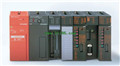
Product model: A1SJCPU
Name: Programmable Logic Controller
Brand: MITSUBISHI
Sort: Common Instructions Programming Manual
File language: English
Download link: MITSUBISHI A1SJCPU Programming Manual
RS-232 2 channel.
Transmission speed: 2 channel total is 115.2kbps.
Equipment layer / field bus CC-Link device layer is the PLC and other control devices and sensors and drive devices connected to the field network,
Network for the lowest layer of the whole network system A1SJCPU PDF.
Using CC-Link field bus connection, the number of wiring is greatly reduced,
Improve the maintainability of the system A1SJCPU
And, not just the amount of data ON/OFF and other switches,
Can also be connected to the ID system, bar code reader, inverter, man-machine interface and other intelligent devices,
From the completion of a variety of data communication, the management of the terminal production information can be realized,
On the centralized management of the state of the machine movement,
Make maintenance work efficiency also greatly improved A1SJCPU PDF.
Q series PLC in the use of CC-Link function better,
And easier to use. Input and output points: 4096 points A1SJCPU PDF.
Input / output data points: 8192 points.
Program capacity: 30K.
Basic command processing speed (LD command) s:0.15.
Integral type: the PLC components are installed together or a few pieces of printed circuit board,
And together with the power supply installed in the casing to form a single overall called the host or the basic unit, small, ultra small PLC using this structure MITSUBISHI Programming Manual A1SJCPU Manual.
Modular: PLC is the basic components of a separate module.
Medium and large PLC used this way. Easy maintenance.
Each scanning process. Focus on the input signal sampling. Focus on the output signal to refresh MITSUBISHI Programming Manual .
Input refresh process. When the input port is closed,
Program in the implementation phase, the input end of a new state, the new state can not be read.
Only when the program is scanned, the new state is read.
A scan cycle is divided into the input sample, the program execution, the output refresh MITSUBISHI Programming Manual .
The contents of the component image register are changed with the change of the execution of the program.
The length of the scan cycle is determined by the three.
CPU the speed of executing instructions.
Time of instruction.
Instruction count.
Due to the adoption of centralized sampling.
Centralized output mode.
There exist input / output hysteresis phenomena, i.e., the input / output response delay.
User program storage capacity: it is aa measure of how much the user application can store the number of indicators A1SJCPU Programming Manual .
Usually in words or K words as units. 16 bit binary number is a word,
Every 1024 words are 1K words. PLC to store instructions and data in words.
General llogical operation instructions each account for 1 words A1SJCPU Manual. Timer / counter,
Shift instruction accounted for 2 words. Data operation instructions for 2~4.
Related products
MITSUBISHI
Master control module
A1SJ71T32-S3
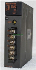
Cale type: twisted pair.
A1SJ71PT32-S3
MITSUBISHI
Network module
A1SJ71QLP21

SI/QSI/H-PCF/ wide H-PCF optical cale d
MITSUBISHI
Temperature control module
A1S62TCTT-S2
Numer of channels: 2 channels.
Sensing
MITSUBISHI
Extension cable
A1SC30B

Cale length: 3 meters
Extending cale t


