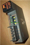
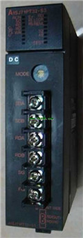
MITSUBISHI A1SJ71E71N-B5 User's Manual PDF
Product model: A1SJ71E71N-B5
Name: Ethernet Interface Module
Brand: MITSUBISHI
Sort: User's Manual
File language: English
Download link: MITSUBISHI A1SJ71E71N-B5 User's Manual
Input type: DC input, positive common end.
Input points: 32 points.
Enter the response time: 1.5ms the following.
Rated input voltage / current: DC24V/5mA A1SJ71E71N-B5 PDF.
External connection: 3 wire.
Spring clip terminal.
Do not need to be tightened further or locked with screws, which can reduce the working hours of wiring.
Using 2 pieces of structure of the terminal units, maintenance can be maintained in the same line under the condition of the replacement module A1SJ71E71N-B5
When installing the module can choose to use the DIN guide rail or screw mounting.
Can be used for the 3 wire sensor input wiring. Type of input: DC leakage A1SJ71E71N-B5 PDF.
Input points: 16 points.
Input voltage: 12/DC24.
Input current: 3/7.
Connection mode: terminal row
Common common point: 16.
The instruction listt programming language is a programming language similar to assembly language mnemonic,
As well as assembly language by the operation code and the number of operations A1SJ71E71N-B5 PDF A1SJ71E71N-B5 Manual.
In the case of the computer for the PLC handheld programmer compile user program.
At the same time, the programming language of the instruction list corresponds to the ladder diagram programming language,
In PLC programming software can be converted to each other MITSUBISHI User's Manual. Figure 3 is the instruction sheet corresponding to the ladder diagram of figure 2PLC.
The characteristics of instruction table programming language is used to represent mnemonic operation function,
Easy to remember, easy to grasp;
In the handheld programmer on the keyboard using the mnemonic representation, easy to operate, can be programmed in computer;
There is a one-to-one correspondence between the ladder diagram and the ladder diagram MITSUBISHI User's Manual. Its characteristics are basically consistent with the ladder diagram language. Horizontally placed cable.
Length: 550mm.
MITSUBISHI PLC program simulation debugging
The basicc idea of program simulation debugging is,
In order to facilitate the form of simulation to generate the actual state of the scene,
Create the necessary environmental conditions for the operation of the program MITSUBISHI User'ss Manual A1SJ71E71N-B5 Manual A1SJ71E71N-B5 User's Manual.
Depending on the way the field signals are generated,
The simulation debugging has two forms of hardware simulation and software simulation.
Related products
MITSUBISHI
MODBUS interface module
A1SJ71UC24-R4-S2

Data format: RTU.
Data its: 8.
A1SJ71UC
MITSUBISHI
Serial communication module
A1SJ71QC24-R2

RS-232 2 channel.
Transfer speed: 0.3-19
MITSUBISHI
Master control module
A1SJ71PT32-S3

Cale type: cale or twisted pair.
A1SJ7
MITSUBISHI
MODBUS interface module
A1SJ71UC24-R2-S2

Data format: ASCII.
Data its: 7.
A1SJ71


