 LK Automation Limited
MITSUBISHI A1SD75P1-S3 User's Manual PDF
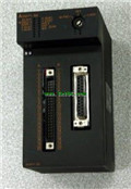
Product model: A1SD75P1-S3
Name: Positioning Module
Brand: MITSUBISHI
Sort: User's Manual
File language: English
Download link: MITSUBISHI A1SD75P1-S3 User's Manual
Remote I/O controller, optical fiber GI.
How to choose MITSUBISHI PLC.
MITSUBISHI PLC options include the choice of MITSUBISHI PLC models, capacity, I/O module, power, etc A1SD75P1-S3 PDF. .
MITSUBISHI PLC distribution I/O points and design MITSUBISHI PLC peripheral hardware circuit
Draw the I/O point of the PLC and the input / output device connection diagram or the corresponding table,
This part also can be carried out in second steps A1SD75P1-S3
Design PLC peripheral hardware circuit.
Draw the electrical wiring diagram of the other parts of the system,
Including the main circuit and the control circuit does not enter the PLC, etc A1SD75P1-S3 PDF. .
The electrical schematic diagram of the system composed of I/O PLC connection diagram and PLC peripheral electrical circuitt diagram A1SD75P1-S3 Manual.
So far the system''s hardware electrical circuit has been determined. Screw, 2 piece type terminal
Platinum temperature measuring resistor body PT100 temperature input module A1SD75P1-S3 PDF.
Number of channels: 4 channels.
Number of stations: 4 stops.
Station type: remote equipment station.
MITSUBISHI PLC online debugging.
On-line debugging is the process that will through the simulation debugging to further carry on the on-line unification to adjust.
On-line debugging process should be step by step,
From MITSUBISHI PLC only connected to the input device, and then connect the output device, and then connect to the actual load and so on and so on step by step MITSUBISHI User's Manual.
If you do not meet the requirements, the hardware and procedures for adjustment.
Usually only need to modify the part of the program can be MITSUBISHI User's Manual.
MITSUBISHI PLC hardware implementation
Hardware implementation is mainly for the control cabinet and other hardware design and field construction.
Design control cabinet and the operating table and other parts of the electrical wiring diagram and wwiring diagram MITSUBISHI User's Manual A1SD75P1-S3 User's Manual.
Electrical interconnection diagram of each part of the design system.
According to the construction drawings of the site wiring, and carry out a detailed inspection.
Because the program deesign and hardware implementation can be carried out at the same time,
So the design cycle of the MITSUBISHI PLC control system can be greatly reduced A1SD75P1-S3 Manual.
Related products
MITSUBISHI
Positioning module
A1SD71-S7
2 axes.
2 axis linear interpolation.
Con
MITSUBISHI
Positioning module
AD75P1-S3
1 axes.
2 axis linear interpolation, 2 a
MITSUBISHI
Positioning control module
A1SD75M2
Axis of control: 2.
Interpolation functi
MITSUBISHI
Pulse output positioning control module
A1SD71-S2
Axis of control: 2.
A1SD71-S2 is a linea


