 LK Automation Limited
MITSUBISHI A1SD61 User's Manual PDF
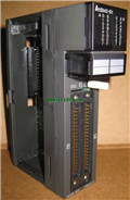
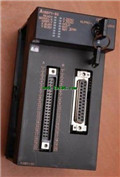
Product model: A1SD61
Name: High Speed Counter Module
Brand: MITSUBISHI
Sort: User's Manual
File language: English
Download link: MITSUBISHI A1SD61 User's Manual
I/O slots: 8 slots.
Outline dimension: 430*130.
CPU basic board can be plugged into 1 power modules,
1 CPU components and a maximum of 2, 3, 5, or 8 single slot size special function components and I/O components are respectively inserted and arranged A1SD61 PDF.
Expansion ports are arranged on both sides of the base plate,
For connecting the expansion board for.
Up to 3 extension substrates. Special multi axis positioning controller for NSD servo system A1SD61
Optical data communication line.
Program capacity: Max 60K step.
Input / output points: 1920 points.
When the switch is off, the diode does not emit light, and the transistor is not on the way A1SD61 PDF. Internal circuit input signal.
It is through the input interface circuit to the external switch signal into PLC internal can accept the digital signal.
Photoelectric three levels: in the light of the light signal conduction, the degree of light signal and the intensity of the lightt signal A1SD61 PDF A1SD61 Manual .
The output signal has a linear relationship with the input signal in the linear operating region of the photoelectric coupler.
User program storage capacity: it is a measure of how much the user application can store the number of indicators.
Usually in words or K words as units MITSUBISHI User's Manual. 16 bit binary number is a word,
Every 1024 words are 1K words. PLC to store instructions and data in words.
General logical operation instructions each account for 1 words. Timer / counter,
Shift instruction accounted for 2 words. Data operation instructions for 2~4.
The length of time required to execute the instruction, the length of the user''s program, the type of instruction, and the speed of the CPU execution are very significant,
Generally, a scanning process, the fault diagnosis time,
Communication time, input sampling and output refresh time is less,
The execution time is accounted for the vast majority of MITSUBISHI User's Manual MITSUBISHI User's Manual.
The photoelectric coupler is composed of two luminous two extreme tubes and a photoelectric transistor.
Light emiitting diode two: the input of a photo coupler and the change of electrical signal,
The light signal is generated by the light emitting diode, which is the same as the input signal A1SD61 User's Manual.
The working process of the input interface circuit: when the switch is closed, the diode light,
The transistor is then guided to the internal circuit and input signal under the irradiation of the light A1SD61 Manual .
Related products
MITSUBISHI
Pulse output positioning control module
A1SD71-S2
Axis of control: 2.
A1SD71-S2 is a linea
MITSUBISHI
Relay output module
A1SY14EU

Output type: relay.
Output points: 12 po


