 LK Automation Limited
MITSUBISHI A1SCPUC24-R2 Programming Manual (Fundamentals) PDF
Product model: A1SCPUC24-R2
Name: PLC
Brand: MITSUBISHI
Sort: Fundamentals Programming Manual
File language: English
Download link: MITSUBISHI A1SCPUC24-R2 Programming Manual
Input and output points: 480 points.
Input / output data points: 480 points.
Program capacity: 8k.
Basic command processing speed (LD command) s:1.25.
RAM memory capacity: 32K, power supply (DC24V) A1SCPUC24-R2 PDF.
Modular: PLC is the basic components of a separate module.
Medium and large PLC used this way. Easy maintenance.
Relay output interface circuit of PLC
Working process: when the internal circuit output digital signal 1,
There is a current flowing through, the relay coil has a current, and then the normally open contact is closed,
Provide load current and voltage A1SCPUC24-R2
When the internal circuit outputs a digital signal 0, there is no current flowing through it,
The relay coil does not have a current, and the normally open contact is broken off,
A current or voltage that is disconnected from the load A1SCPUC24-R2 PDF.
It is through the output interface circuit to the internal digital circuit into a signal to make the load action or not action A1SSCPUC24-R2 PDF A1SCPUC24-R2 Manual .
User program storage capacity: it is a measure of how much the user application can store the number of indicators.
Usually in words or K words as units. 16 bit binary number is a word,
Every 1024 words are 1K words. PLC to store instructions and data in words.
General logical operation instructions each account for 1 words MITSUBISHI Programming Manual. Timer / counter,
Shift instruction accounted for 2 words. Data operation instructions for 2~4. Type of input: DC source.
Input points: 16 points.
Input voltage: DC24.
Input current: 7mA.
Connection mode: terminal row.
Common common point: 16 MITSUBISHI Programming Manual.
Functional block diagram language is a kind of PLC programming language, which is similar to digital logic circuit.
The function module is used to represent the function of the module,
Different function modules have different functions.
Functional module figure programming language features: functional block diagram programming language is characterized by a functional module for the unit,
Analysis and understanding of the control scheme is simple and easy: function moddule is to use graphical form of expression,
Intuitive, for a digital logic circuit based on the design of the staff is very easy to master the programming;
Control system with complex scale and complex control logic,
Because thhe function module diagram can clearly express the function relation, the programming debugging time is greatly reduced MITSUBISHI Programming Manual A1SCPUC24-R2 Manual A1SCPUC24-R2 Programming Manual.
Related products
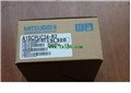
MITSUBISHI
Computer communication module
A1SJ71UC24-R2
Interface: RS232C.
Transmission distance
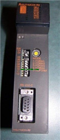
MITSUBISHI
CPU component with built-in RS232C interface
A1SCPUC24-R2
A1SCPUC24-R2 integrates all functions of
MITSUBISHI
Serial communication module
QJ71C24-R2
"2CH RS-232.
QJ71C24N -R2 through the
MITSUBISHI
Serial communication module
RJ71C24-R2
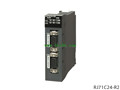
230.4kps Max., RS-232 2 channel.
When u


