 LK Automation Limited
MITSUBISHI A1S68TD User's Manual (Hardware) PDF
Product model: A1S68TD
Name: Thermocouple Input Module
Brand: MITSUBISHI
Sort: Hardware User's Manual
File language: English
Download link: MITSUBISHI A1S68TD User's Manual
Series Name: A953GOT.
Size: 6 inches.
Resolution: 320 * 240.
Display device: STN color display.
Display color: 8 color.
Power supply: DC24V.
The built-in RS-232 communication interface A1S68TD PDF.
Memory card: 1M.
Design any machine interface, generally have to consider the system response time, user assistance mechanism, error information processing and command mode four aspects.
System response time is too long to be the most users in the interactive system,
In addition to the absolute length of the response time, the user is also very concerned about the difference in response to different commands in response time,
If too wide users will be difficult to accept; user assistance mechanism should be integrated,
Avoid overlay systems that cause users to turn to a guide and have to browse a large number of irrelevant information;
Error and warning information must be selected in terms of user''s clarityy and meaning,
At the same time, it should be as far as possible to provide some suggestions on the recovery of errors A1S68TD PDF A1S68TD PDF A1S68TD Manual A1S68TD
In addition, when the error message is displayed, the effect is better if it is supplemented by the auditory (Bell) and visual (special color) stimulus;
Command mode is the best menu and keyboard commands, for the user to choose MITSUBISHI User's Manual. QnA/ACPU bus connection.
1 joint.
Applicable model: A956WGOT. 32 point connector for compressed flat cable (37 pin D-Sub connector).G1-62.5/125 fiber optic cable.
Double loop.
PC inter network (management station / station) / remote I/O network (remote control station) MITSUBISHI User's Manual.
How to choose MITSUBISHI PLC.
MITSUBISHI PLC options include the choice of MITSUBISHI PLC models, capacity, I/O module, power, etc..
MITSUBISHI PLC distribution I/O points and design MITSUBISHI PLC peripheral hardware circuit
Draw the I/O point of the PLC and the input / output device connection diagram or the corresponding table,
This part also can be carried out in second steps MITSUBISHI User's Manual.
Design PLCC peripheral hardware circuit A1S68TD User's Manual.
Draw the electrical wiring diagram of the other parts of the system,
Including the main circuit and the control circuit does not enter the PLC, etc..
The electrical schematic diagram of the system compoosed of I/O PLC connection diagram and PLC peripheral electrical circuit diagram A1S68TD Manual .
So far the system''s hardware electrical circuit has been determined.
Related products
MITSUBISHI
Input module
A1SX40-S1
Type of input: DC leakage.
Input points:
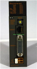
MITSUBISHI
Ethernet module
A1SJ71QE71N-B2
10BASE2.
Q mode.
MITSUBISHI PLC is the m
MITSUBISHI
Extended bottom plate
A1S55B-S1
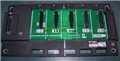
I/O slots: 5 slots.
Can you install the
MITSUBISHI
Ethernet module
A1SJ71E71N-B5
10BASE5.
PLC is introduced y the relay


