 LK Automation Limited
MITSUBISHI A171SCPU Programming Manual (Dedicated Instructions) PDF
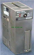
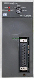
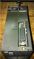
Product model: A171SCPU
Name: PLC
Brand: MITSUBISHI
Sort: Dedicated Instructions Programming Manual
File language: English
Download link: MITSUBISHI A171SCPU Programming Manual
DC input points: 2 points.
Input voltage and current: 7mA, DC24V.
Input response time: 10ms.
2 point /1 a public side.
Positive pole sharing.
Output points: 2 points A171SCPU PDF.
Output voltage and current: DC24V.
Output response time: 2ms.
2 point /1 a public side.
Output form: transistor output, leakage type.
16 point terminal station.
MITSUBISHI PLC protection and chain procedures.
Protection and chain is an indispensable part of the program, must be carefully considered A171SCPU
It can avoid the control logic confusion caused by illegal operations.
MITSUBISHI PLC initialization procedure. After MITSUBISHI PLC on power, the general need to do some of the initial operation,
In order to start making necessary preparations, to avoid the wrong operation of the system A171SCPU PDF.
The main contents of the initialization program are: to some data area, counter and so on,
Data needed to restore some of the data area,
Set or reset some relays,
For some initial state display, etc A171SCPU PDF. .
MITSUBISHI PLC program simulation debugging
The basic idea of program simulation debugging is,
In order to facilitate the form of simulation to generate the actual state of the scene,
Create the necessary environmental conditions for the operation of the program MITSUBISHI Programming Manual.
Depending on the way the field signals are generated,
The simulation debugging has two forms of hardware simulation and software simulation. A3VTS using the basic unit.
Relay output interface circuit of PLC
Working process: when the internal circuit ouutput digital signal 1,
There is a current flowing through, the relay coil has a current, and then the normally open contact is closed,
Provide load current and voltage MITSUBISHI Programming Manual A171SCPU Manual .
When the internal circuit outputs a digital signal 0, there is no current flowing through it,
The relay coil does not have a current, and the normally open contact is broken off,
A current or voltage that is disconnected from the load MITSUBISHI Programming Manual.
It is through the output interface circuit to the internal digital circuit into a signal to make the load action or not action.
When the programmer input programinto the user program memory,
Then CPU according to the function of the system (the system program memory to explain the compiler),
Translate the user program into PLC internally recognized by the user to compile the program.
I/O points is an important indicator of PLC.
Reasonable selection of I/O points can not only satisfy the control requirements of the system,
And the total investment of the system is the lowest.
The input and output points and types of PLC should be determined accoording to the analog quantity and switch quantity of the controlled object,
Generally an input / output element to take up an input / output point A171SCPU Programming Manual.
Taking into account the future adjustment and expansion,
In general should be estimaated on the total number of points plus the amount of spare 20%~30% A171SCPU Manual .
The following describes the centralized control system I/O points of the estimate.
Related products
MITSUBISHI
CPU unit
A1SCPU
Program memory capacity: 8k.
Input / out
MITSUBISHI
CPU unit
A2SCPU
Program memory capacity 14K.
Input and o
MITSUBISHI
Motion controller
Q170MSCPU
Control axis: up to 16 axes.
Interpolati
MITSUBISHI
CPU unit
A2USCPU
Input and output points: 512 points.
Inp


